First off I’d like to tip my hat to Makerbot for coming up with such an amazing original. We’re talking some mad design skills here.
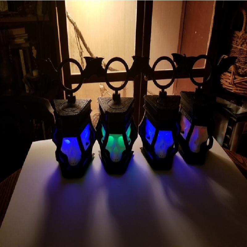
That said when I first saw this I felt it was not quite done yet. It is a lantern with no light. I knew it could be improved upon. With clear plastics on the market, certain models are just begging for LEDs. This was no exception. In fact it screamed for more than just a few simple LEDs to make it glow. It needed to be able to come alive!
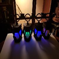
It was finally time to teach myself the basics of C and really utilize the Arduinos I’d been ordering just in case I had a project for them. What I came up with was set up with 2 RGB LEDs behind the eyes and an Arduino sketch that pulses with varying combinations of 6 colors for 130 preset options! True red and green come up with a color just a little off from straight green so I might have been stretching on the colors, but it’s a sick green and I like it!
Sample of Functions
Mods to the original files.
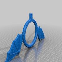
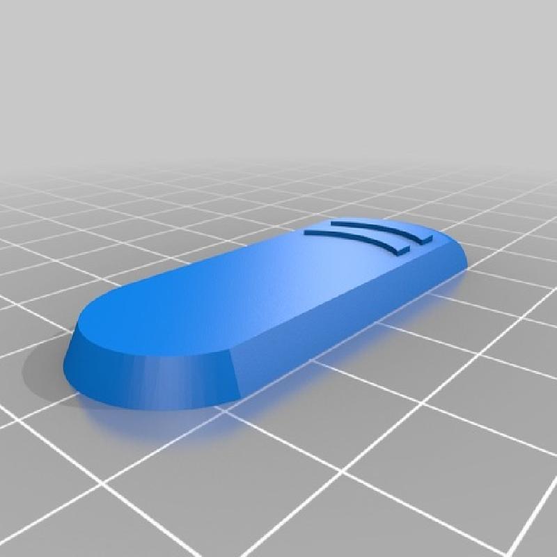
This first thing I did was add a couple of hollow cylinders to the skull with the help of TinkerCad. My 3d skills are limited, but I knew I could bury a couple of RGB LEDs behind the eyes.
While I was printing the skulls (I decided to give away a bunch of these to friends and family.) I began teaching myself C. It was on my agenda anyway as I had been collecting Arduino Uno boards and RGB LEDS with plans to figure out how to use the PWM pins on the Arduinos.
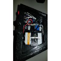
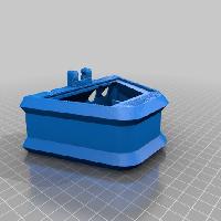
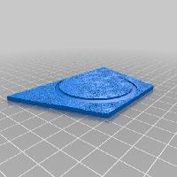
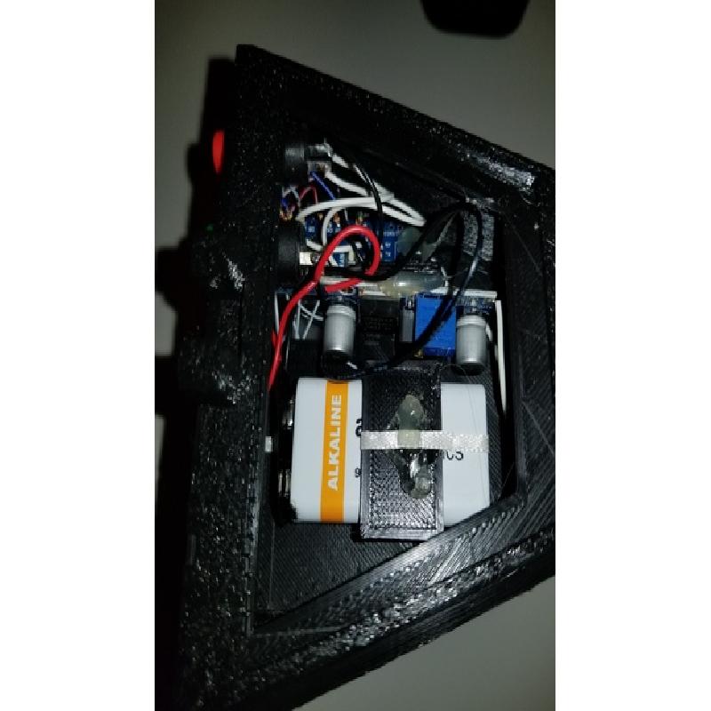
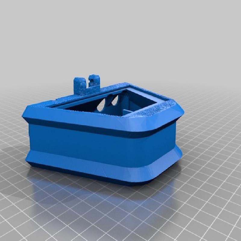
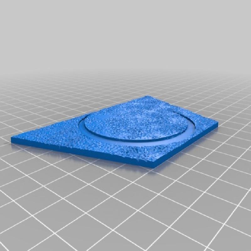
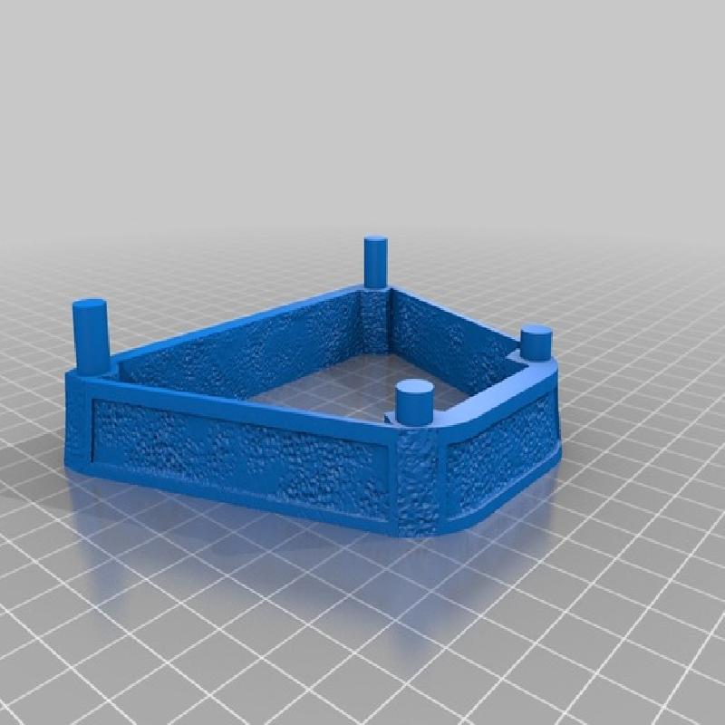
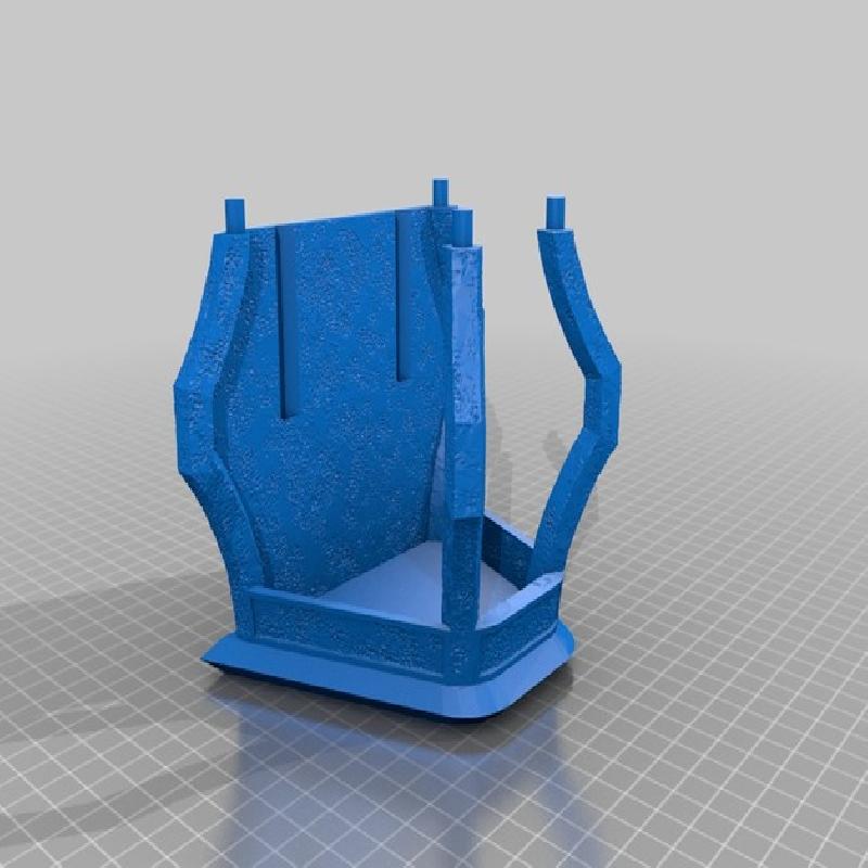
The Lantern Top file had enough room for the electronics, so using TinkerCad again, I hollowed it out, added a mount for the Arduino, two holes for switches, a plane to glue the regulator board to, a holder for the 9 volt battery, and a door to access the battery. I also cut a lid out of the model and added supports within the compartment to glue the lid to.
Requirements and assembly.
So a run down on the extras you’ll need:
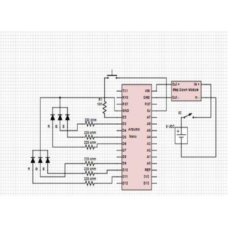
1.) An Arduino Nano (I know I was playing with the Unos when I started but the Nanos function fine in a smaller space.)
2.) A DC-DC Buck Step Down Converter Module LM2596 Voltage Regulator. We’re going to run the Nano off a 9 volt battery, but we the Arduino runs on 5v. I purchased 10 of them at once because a, they’re cheaper and I’ll use them, and b, I’m planning on giving ½ a dozen of these away.
http://www.ebay.com/itm/10-PCS-DC-DC-Buck-Step-Down-Converter-Module-LM2596-Voltage-Regulator-US/122642781277?ssPageName=STRK%3AMEBIDX%3AIT&_trksid=p2057872.m2749.l2649
3.) (6) 220ohm resistors.
4.) (1) 10k ohm resistor.
5.) (2) Common Cathode RGB LEDs.
6.) (1) Normally open momentary push button switch for a 12 mm hole.
7.) (1) self locking push button spst on/off switch for a 13 mm hole.
8.) (1) 9 volt battery clip
9.) (1) USB Mini-b 5 pin data cable. You’ll need this to flash the Arduino. A micro cable like an Android charging cable is the wrong one. If you don’t have one order one. The odds are you won’t find one locally.
10.) 22 to 28 gauge hookup wire.
11.) A soldering iron with a fine tip and fine solder.
12.) A Multimeter.
13.) An assortment of heat shrink tubing. You can get an assorted pack off Ebay cheap. You’ll have a lot left over, but that’s a good thing!
14.) Super glue for assembly. I imagine one could use hot glue, but be careful about melting too much of your model. I actually use a 3d pen with PLA like a hot glue gun!
Okay, so get printing. I actually cranked mine out at .2mm thickness with an Anet A8 printer. I didn’t use any fill, nut I used supports everywhere with Cura to make sure the wholes didn’t sag. Also with the mods to the top for the electronics, you have to have supports.
While it is printing you can get most of the soldering done. If you’ve never done any soldering before get an extra board or two and practice. Watch some Youtube videos on how to solder fine electronics first. The boards are about $3 and it’s worth having one to practice on.
You are going to want to solder the wires to the DC-DC Buck step down board first. You can solder the batter clip’s black lead directly to the negative input. Use a piece of hookup wire for the positive. This will be passed through the hole for the power switch later.
Once you have the output wires soldered to the break out board as well you’ll want to hook the output to your multimeter. Twist the positive in put wire to the positive battery clip wire and plug in the battery. Use a jeweler’s screwdriver and adjust the screw on the break out board until the multimeter shows you are getting 5 volts. Now you can continue with the soldering.
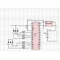
Remember don’t solder the wires to the switches, you’ll need to pass those through the holes so you can insert the switched after soldering. Just follow the schematic. It’s not a complicated circuit. You might want to google the pin out on your RGB LEDs to be sure you get them right the first time. You’ll want your LEDs to be 12mm long so they can reach into the skull. Be sure to slide the heat shrink tubing on the wires BEFORE soldering! Also make sure you have them far enough from your solder points that they don’t shrink from the soldering iron.
Okay once you’ve done most of the soldering and have your top piece/electronics compartment printed run the wires for the button and the power switch through the holes. Remember the on/off button is the larger of the two holes. Solder up the switches. With the monetary switch I used it was a firm enough fit that I didn’t have to use the looking nut. The on and off button did require the nut.
You are ready to upload the sketch to make them run. Upload the sketch before you do your finally assembly. You want to test functionality before gluing everything in place! If you get Red, Blue, and Green out of both LEDs in the first 3 button presses, then your soldering skills have passed the test!
If you don’t know how to upload a sketch to Arduino, start Googling! After all, 3 weeks ago I didn’t know how to write a sketch for Arduino! Anyway the sketch can be found here:
https://gist.github.com/Quietfire/1f0ae6e8a05f17288bb93a77dae9be77
Okay, now that everything is tested and working, finish the assembling. Slide the LEDs into the holes in the Skull. It really doesn’t matter which LED goes in which hole. I used a spot of hot glue to secure both the Arduino and the Step Down Buck board. There is a hole where you can still plug into the Arduino after assemble. This is so you can reprogram it if you want to modify the sketch. Also you can run the lantern off USB to save battery life. Just remember the switch only works for the battery.
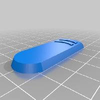
I also glued a piece of ribbon to the top of the battery mount. When I slide the battery in, I do it so the battery pushes the ribbon back and leaves a little hanging out that you can use to pull out the battery.
Glue the lid on and put the handle in place. You’re done! Enjoy. And PLEASE post your builds!