by MazaaFIN, published
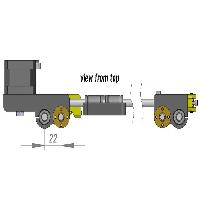
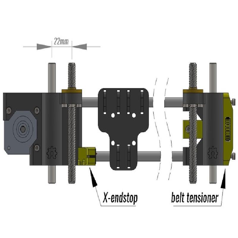
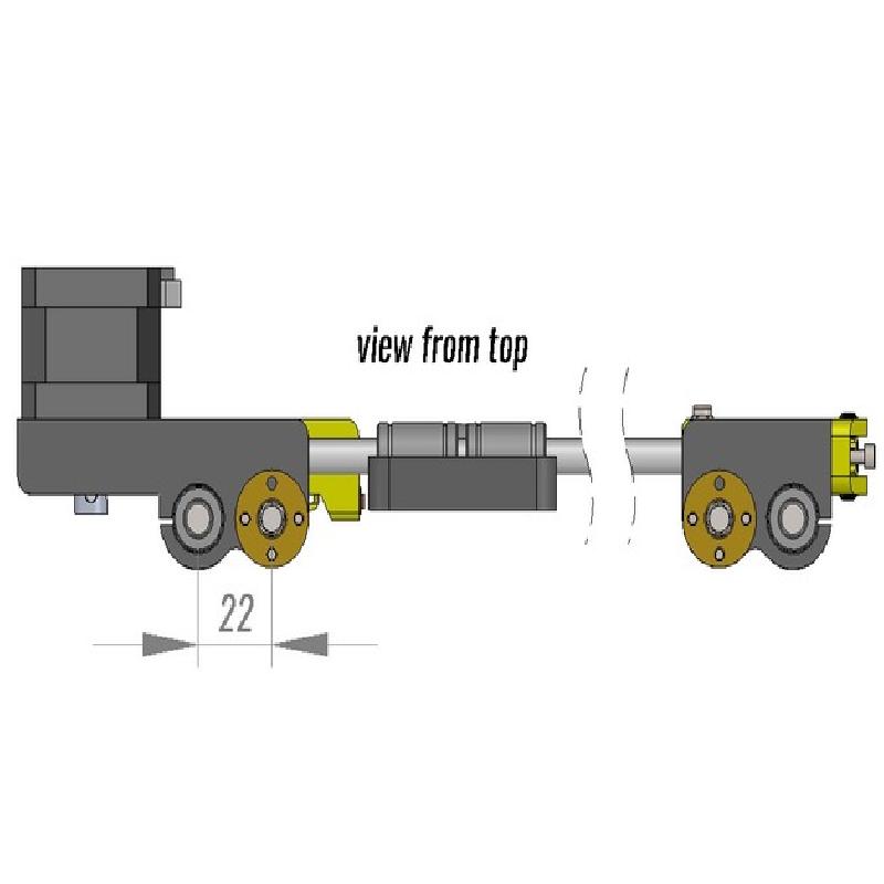
NOTE: X-MOTOR.STL and X-IDLER.STL are made for 22mm spacing
UPDATE 14.2.2016
made parts with 21mm spacing for Geeetech i3 pro c
UPDATE 29.12.2015
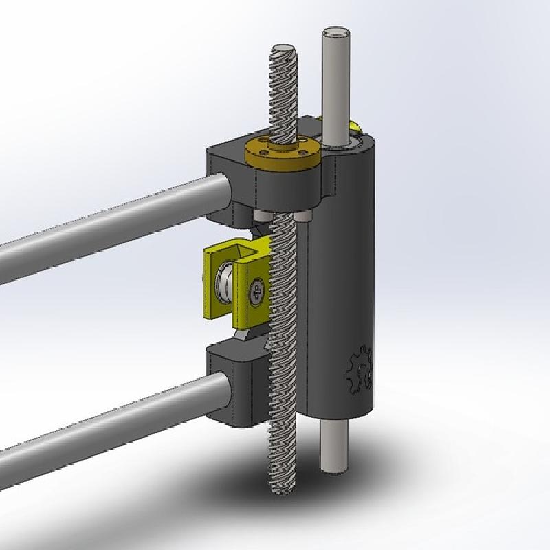
I had identified wrongly the idler bearings my printer came with. They're F693ZZ, not F623ZZ. With latter GT2 belt could not move freely. I have modified the clearance of the belt tensioners arm part so that both bearings should now work.
Updated belt tensioner arm part is added as own file for those that have printed the complete set before.
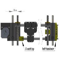
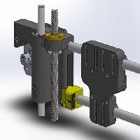
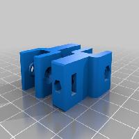
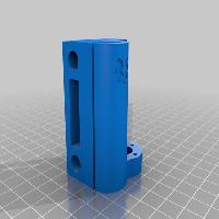
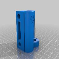
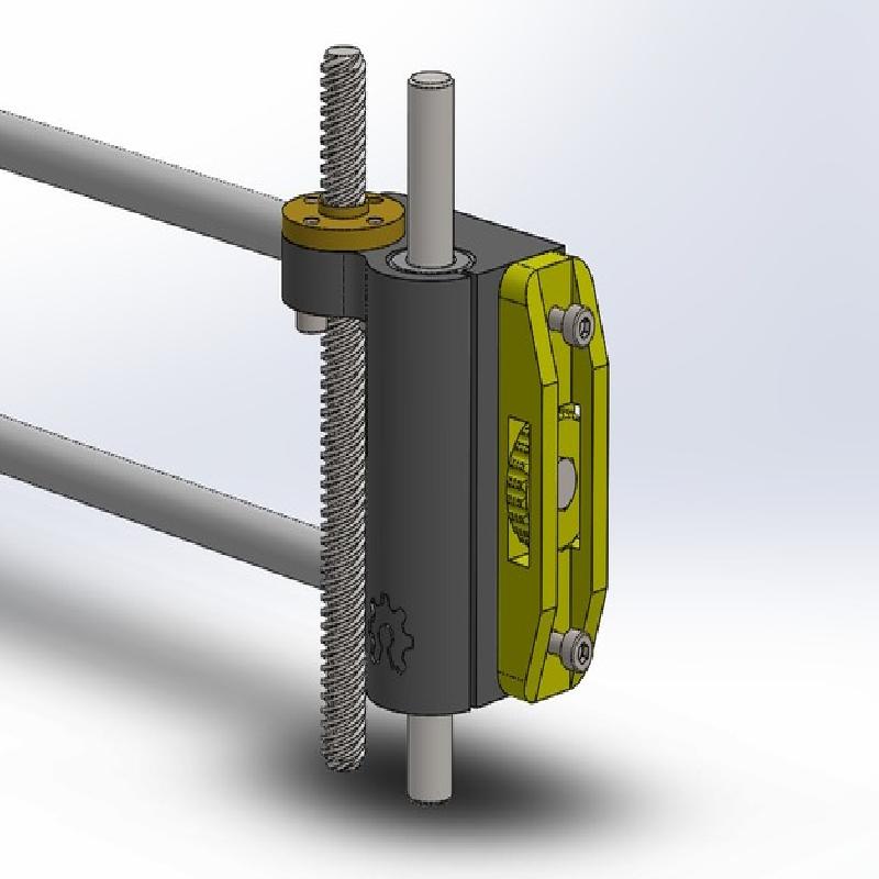
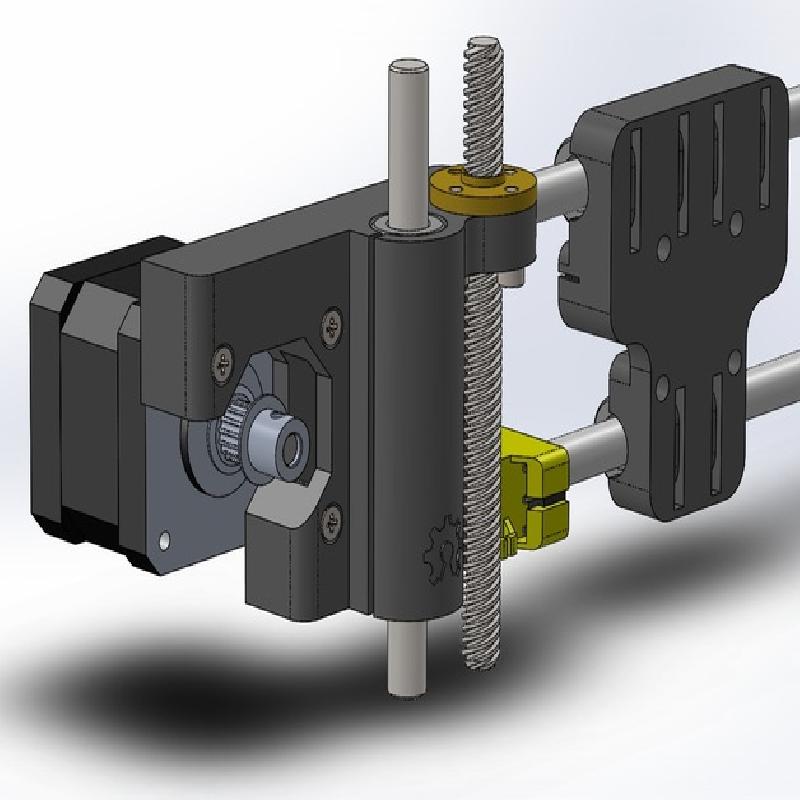
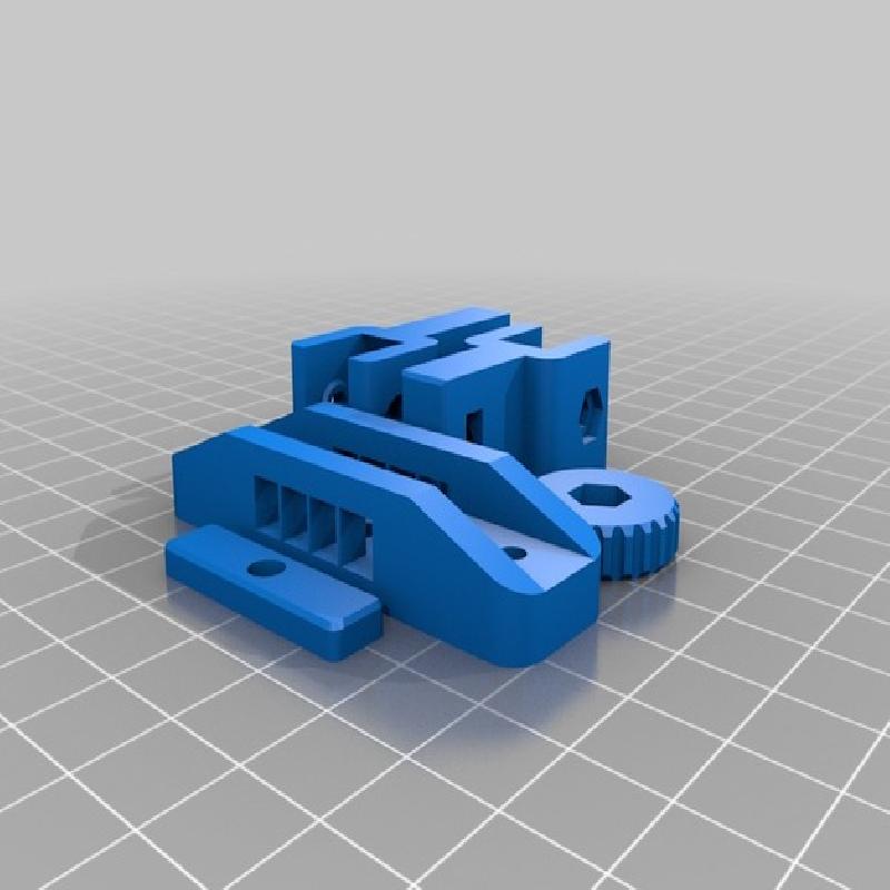
X-axis with fixed X-endstop and finger adjustable belt tensioner. Nothing new compared to already published (like ffleurey's thing:169636 and jkoljo's thing:372056). It's just this smooth looking design I like and wanted to share it.
Note that there's no spesific Z-endstop trigger point as I prefer inductive proximity switch (mounted with the extruder).
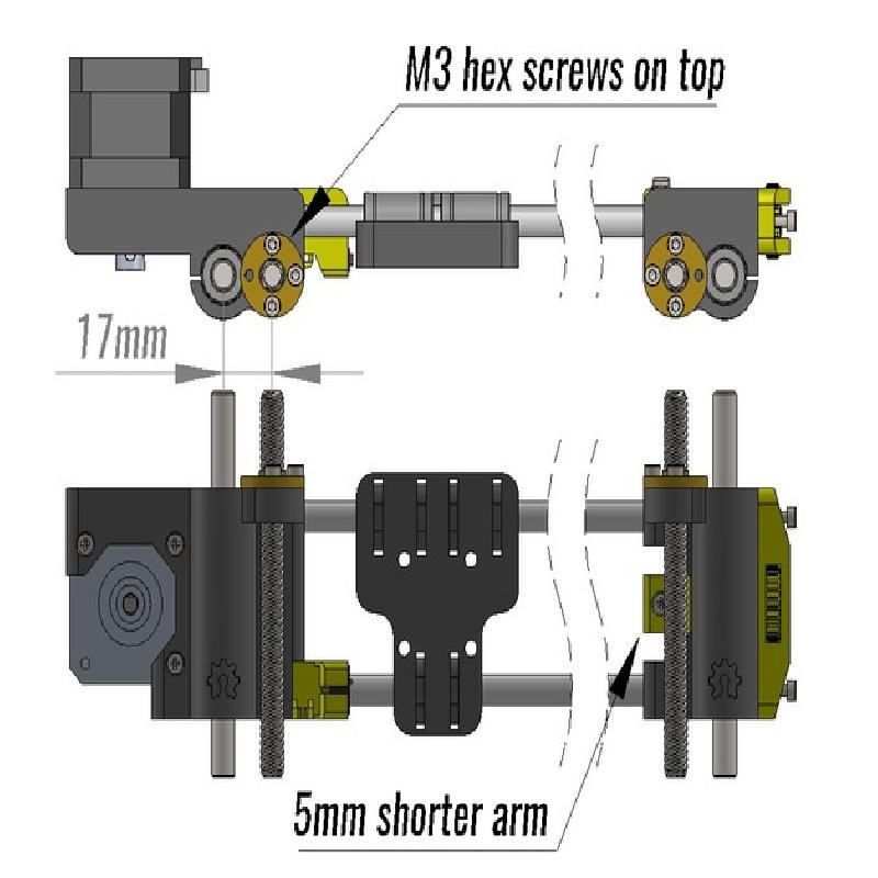
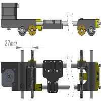
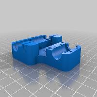
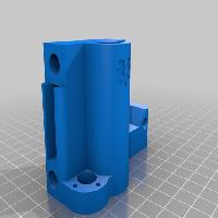
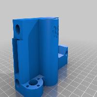
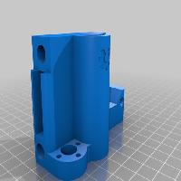
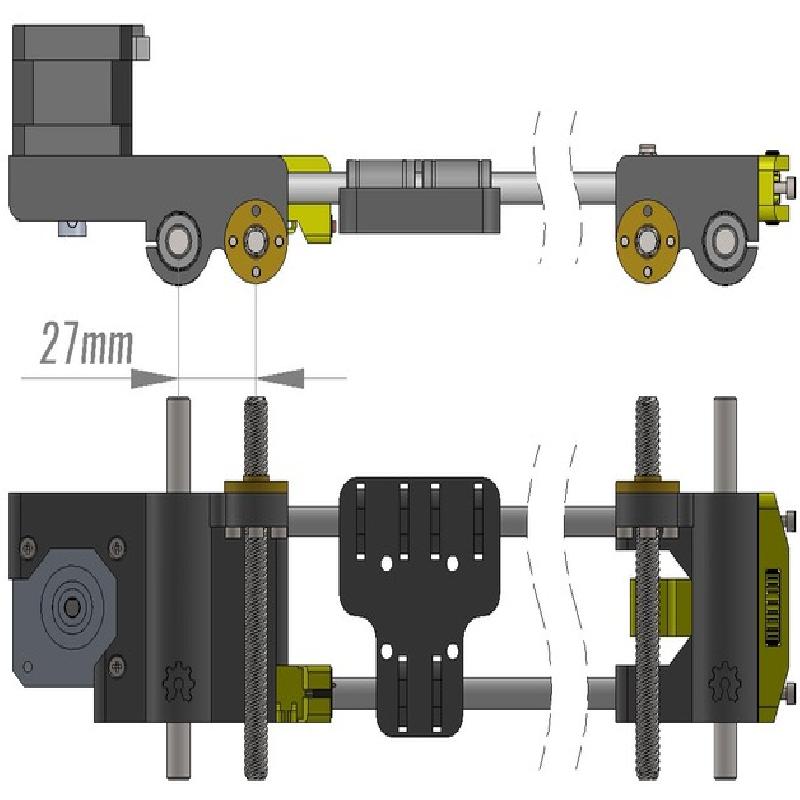
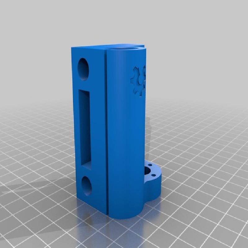
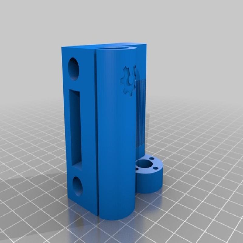
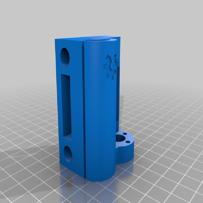
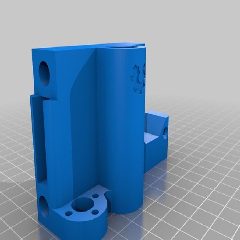
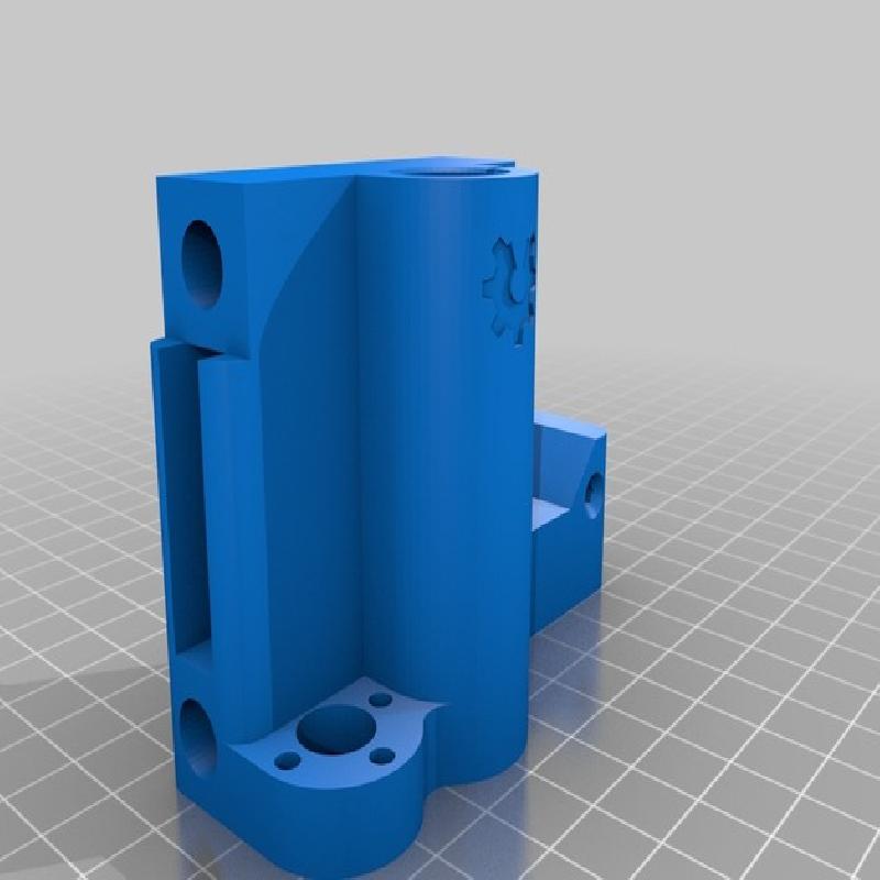
The distance between Z-axis's smooth rod and leadscrew is not same in all Prusa i3 versions. The kit I bought from Aliexpress.com is having 8mm acrylic frame and designed with 22mm distance but it seems that 17mm is more common. Also in Geeetech I3 X the distance is different, 27mm.
I have made necessary modifications and now there's X-motor and X-idler for 17mm, 21mm and 27mm distance too. Please inform me if the design has any faults.
stepper motor mounting point is moved 5mm to the left in X-MOTOR_27mm (Geeetech I3 X)
GT2 belt ends should stay in place without zip-ties. My printer is fixed in enclosed cabinet so belt removal is easier and doesn't require removal of X-carriage.
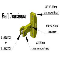
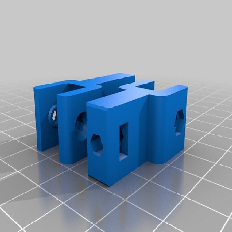
2 x F623ZZ (3x10x4) or F693ZZ (3x8x4) flanged bearing (idler)
4 x M3 20mm recessed head screw (stepper + idler)
1 x M3 nyloc nut (idler)
6 x M3 12mm hex socket screw (leadscrew nuts)
2 x M3 10-16mm hex socket screw (tensioner)
2 x M3 nut (tensioner)
1 x M4 20-30mm hex screw (tensioner)
1 x M4 nut (tensioner)
Rafts: No
Supports: No
Resolution: 0.2 - 0.25 mm layer height
Infill: 30% honeycomb
Notes:
All parts have necessary built-in supports. X-idler's "comb"-supports are 0.5mm width. If slicing generates problems with these, try to change default extrusion width to ≤0.5mm.
Supports should be easily removable. X-endstop has tiny supports, that I carefully cut out with small blade.
If you find there's not enough room for smooth rod, carefully ream the holes with 8mm drill bit. Design clearance is only 0.05mm.
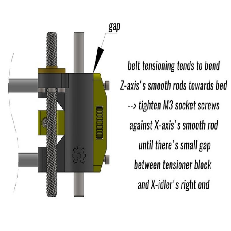
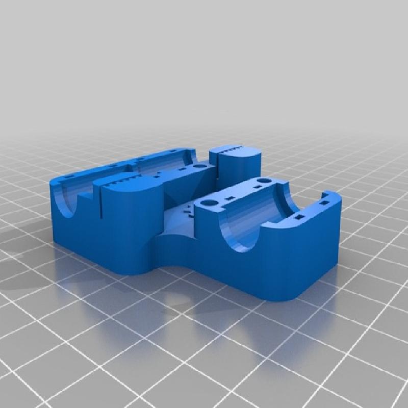
Note that X-axis's smooth rod may not be exactly coincident with X-idler's right end when assembled. It is essential that there's no bending of Z-axis's rods when X-axis moves along it. Take your time to achieve this before tensioning X-belt.
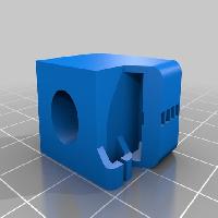
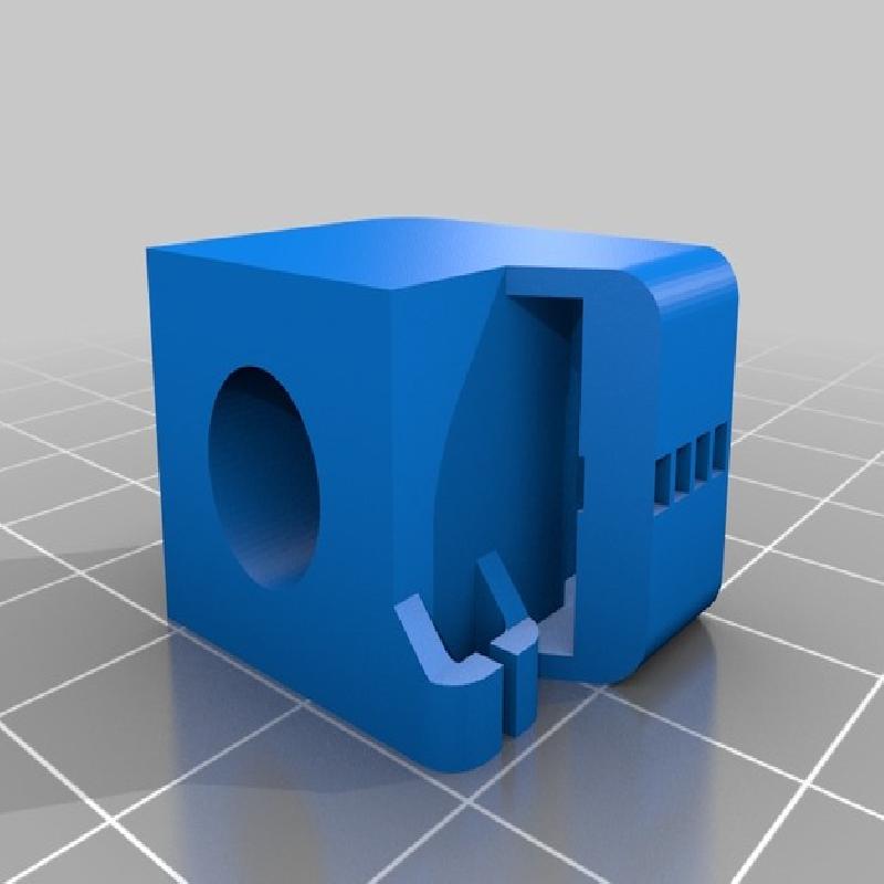
Belt tensioner block has separate guidance piece that should be glued in right place. Make sure there's no binding between this piece and mating hole in X-idler's right end when assembled. Idler bearing holder should also move without binding. Design clearance is 0.25mm in all sides.
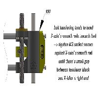
Before adjusting belt tension, make sure there's small gap between tensioner block and X-idler's right end to prevent bending the Z-axis's smooth rods and leadscrew