by chriswh86, published
Since the start of my obsession with 3D printing and computer aided design, Motorsports has been on my mind. The Educational Brake Caliper is my first Motorsports related design to be released to the public.
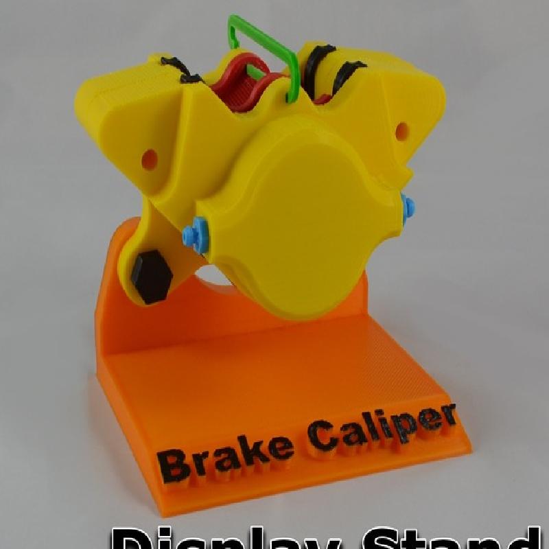
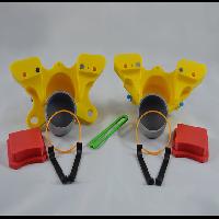
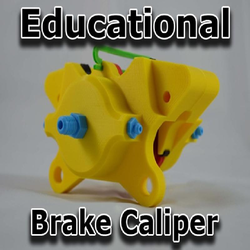
This caliper is based on a race car style brake caliper featuring quick release brake pads and dual pistons. This caliper is FULL SIZED and was modeled off of a Dwarf Car style Race Car.
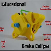
Instead of uploading a somewhat complicated design to Pinshape and letting you try to figure out what you have, I've opted to include some significant documentation so that this caliper can be shown and used as a hands-on educational piece. The document can be found with the STL files and is labelled, 'EducationalBrakeCaliper-Final.pdf'.
Along with it being based on an educational design, this caliper fits perfectly on a shelf or a desk as a display showing all of its intricacies with the included display stand.
My intent with the documentation provided will be to help you with printing, assembling, understanding, teaching and testing with this caliper. My suggestion would be to have you thumb through the document before starting this print so you have an idea on how it should go. Thank you ☺
☼ Check out the video I have done of the caliper being taken apart and re-assembled below! ☼
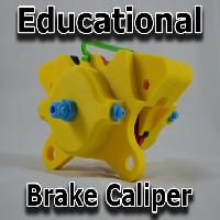
Educational Brake Caliper
* Featured on Thingiverse, April 8th, 2016!
* The Educational Brake Caliper took 1st place in the IC3D Print Contest!
IC3D Print Contest Winners Announced
* Featured in February 26th Staff Picks - Pinshape
Best 3D Printing Designs on Pinshape week of Feb 26th
The complete Brake Caliper project was designed in Autodesk Fusion 360
Tolerances are important when 3D Printing. The tough part is ensuring your print will work with everyone's desktop 3D printer. This can be quite a challenge.
With the Educational Brake Caliper, the fit of most pieces of the caliper were set with ~.2mm tolerances.
My initial planning of the Brake Caliper was to have the ability to pull the caliper part, pull the pieces off and re-assemble so you can see the inner workings and all of the components of the Brake Caliper. I was able to put my planning to practice with this caliper!
Objectives:
The objectives with the Educational Brake Caliper is to allow students to learn how an automotive brake caliper actually functions.
We used vehicles every day, do we fully understand what we are sitting in each day we go to work, to school, to see our loved ones? While the brake caliper is a small piece to the puzzle of a vehicle it is a very critical component.
Because the caliper can be pulled apart and re-assembled, students will have a hands on & visual understanding of the caliper and how each component functions.
Audiences:
The Brake Caliper is a great tool for students 9 years and older.
Automotive classes where this caliper can be displayed & reviewed.
The Brake Caliper can also appeal to anyone getting started in 3D Printing and Modelling.
Preparation:
Printing & Assembly
Here I will go over some tips on getting your prints setup correctly and assembled into working order. I will go over some of the tools used during my process of assembling the caliper. If at any time you aren't sure about which piece of the caliper is being discussed. Please reference the information on pages 20-22 of the EducationalBrakeCaliper-Final.pdf
Necessary & Suggested Hardware:
Magnets:
(Necessary)
The first and main component needed for this build aside from your printer and filament will be Neodymium Disc Magnets. No need to stress though as these magnets are small and cheap! These N52 magnets measure in at ¼” diameter and 1/16” thick.
They can be found all over eBay as well or your favorite magnet store, you’ll want to look for N52 ¼”(dia)x1/16”(thick) Disc Magnets. Each magnet has about 1.5 pounds of pulling force. You should stick to magnets giving you at least ~1.47 pound pulling force or greater.
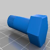
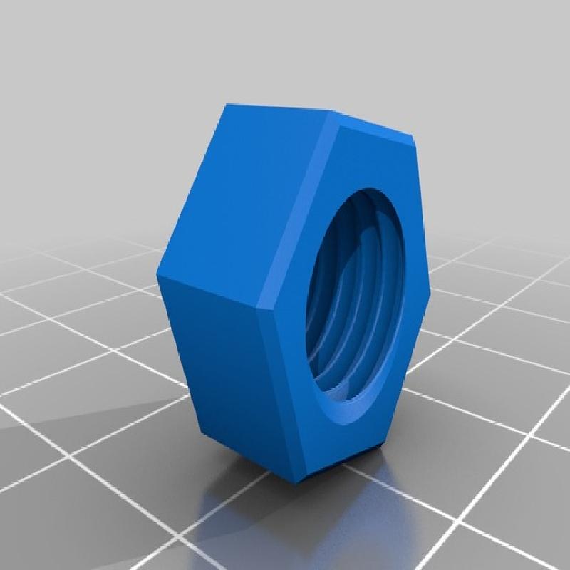
An additional way to mount the two caliper halves together is with the use of bolts through the existing caliper mount holes. You will need M8x50mm hex head bolts (2) and two nuts to fit. This method will require a bit more work during dis-assembly.
Super Glue/Epoxy:
(Necessary)
Some super glue is necessary to attach the bleed screws, magnets and the brake fluid inlet fitting. I have been using Gorilla Super Glue. While it has worked good so far with the bleed screws and inlet fitting I have run into issues with the magnets staying in place after repeated use. My magnets and the bed they sit in were not prepped before gluing. With proper prep and any super glue or even epoxy, you should not have any issues. You can find more information on pages 12-15 of the EducationalBrakeCaliper-Final.pdf
Sand Paper:
(Necessary)
A bit of sandpaper will be necessary when fitting the piston seal and the piston into the piston bore. I typically used 160 grit and 320 grit.
Jewelers File Set:
(Suggested)
While these aren't needed they are a huge help. This caliper was designed with a reasonably tight tolerance to ensure everything sticks together and doesn't fall apart on the floor. The jeweler's files have the necessary files to get into the holes to help expand them to fit the next components. My biggest needs for the files were to enlarge the pad retainer clip where it passes through each caliper half, the wear plates, brake fluid inlet fitting and the brake pads where the retainer clip passes through.
These are a great addition to anyone's 3D printing arsenal as well.

Jewelers File & Super Glue used
Steps: Print Orientation & Settings
In this section I am going to include a screenshot from each STL file when it was loaded into Simplify3D so you can see the orientation used when I printed the parts. You will also find some of the key settings used during the prints. PLA was used for most parts of the caliper with minimal ABS parts that will see distortion during use.
Here is the Simplify3D legend so you can see what each color represents when looking at the graphics below.

Above is the legend for the following sliced images.

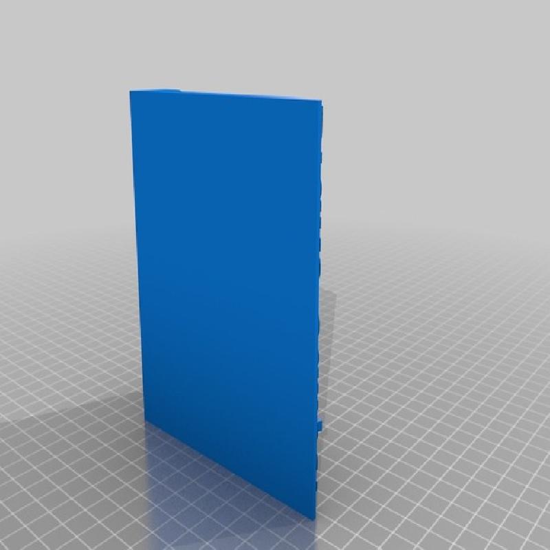
Caliper Non-Mount Side
Print Settings:
Supports at max overhang 45 degrees
.2mm layer
2 outlines/perimeters
30% infill
Printed in PLA (Yellow)
Final Thoughts:
Infill percentage could be dropped to decrease print time. Depending on your printer's capabilities, supports can be removed from some of the easier to print holes etc. Increasing the max overhang angle from 45 will reduce the amount of support needed. You’ll need to manually remove supports you don't want.

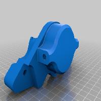
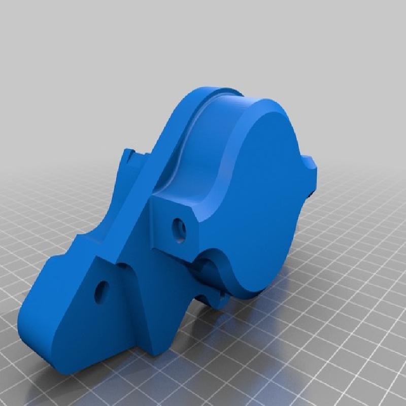
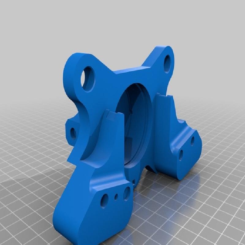
Caliper Mount Side
Print Settings:
Supports at max overhang 45 degrees
.2mm layer
2 outlines/perimeters
30% infill
Printed in PLA (Yellow)
Final Thoughts:
Infill percentage could be dropped to decrease print time. Depending on your printer's capabilities, supports can be removed from some of the easier to print holes etc. Increasing the max overhang angle from 45 will reduce the amount of support needed. You’ll need to manually remove supports you don't want.

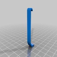
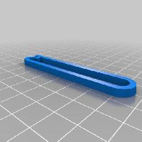
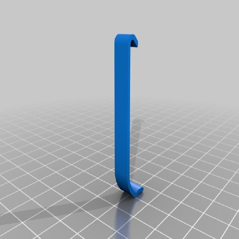
Pad Retainer
Print Settings:
.1-.2mm layer height
1 outline/perimeter
30% infill
Printed in ABS (Green)
Final Thoughts:
It is best to print this item in ABS or a semi-flexible material. During caliper disassembly, this Pad Retainer clip will see frequent bending.

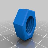
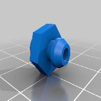
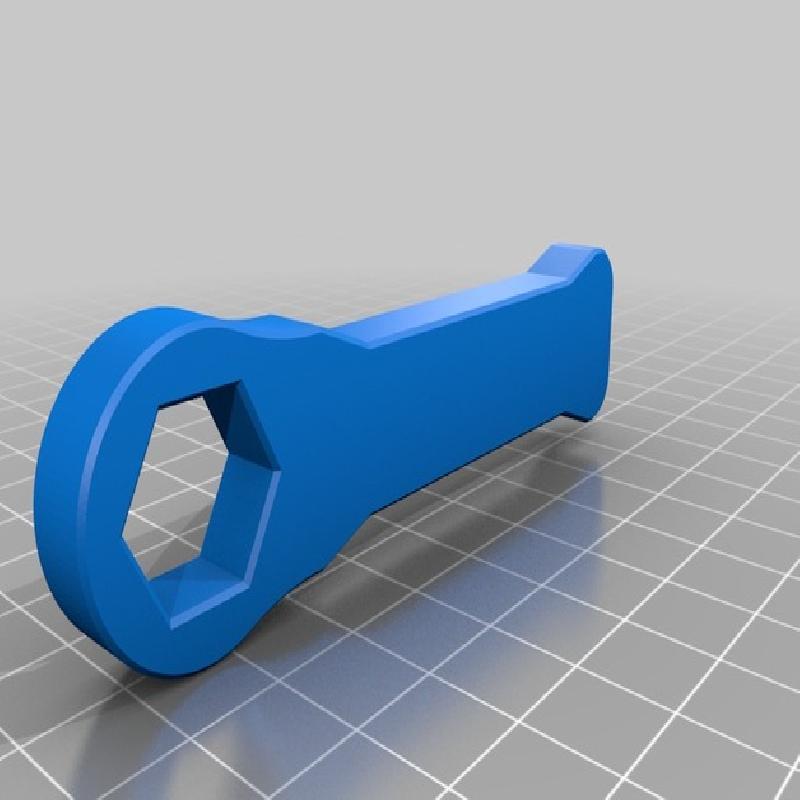
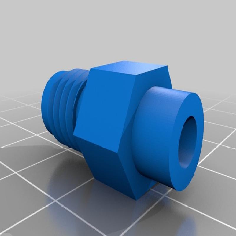
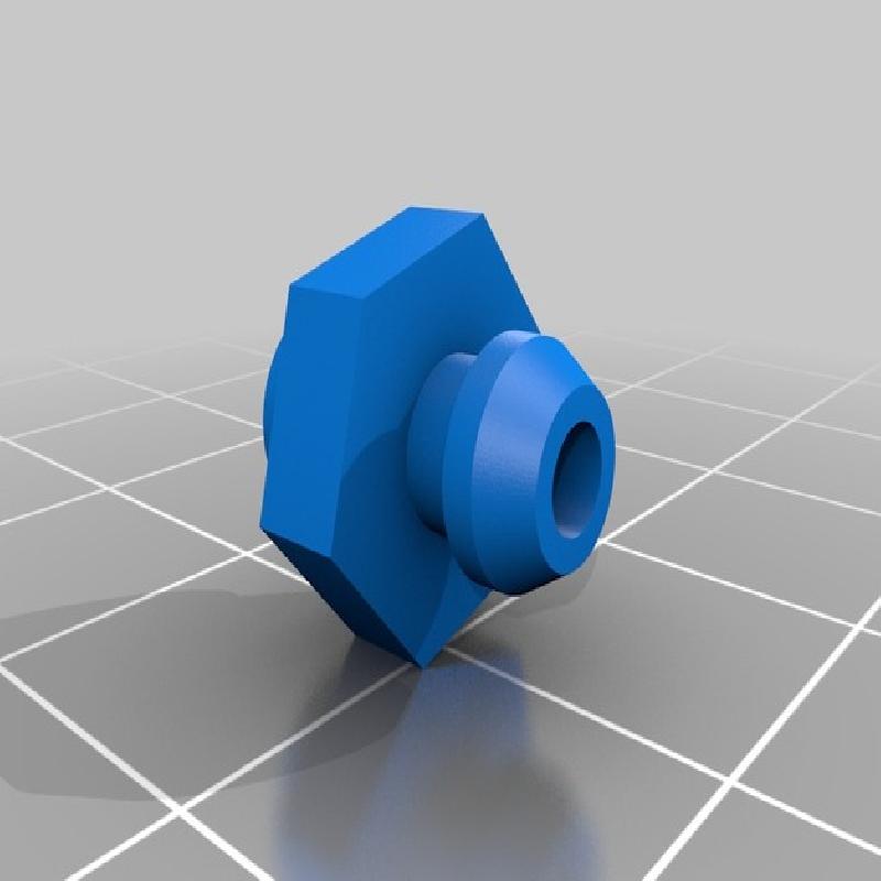
Bleed Screw & Brake Fluid Inlet Feed
Print Settings:
.1mm layer height
Supports
1 outline/perimeter
Raft - Offset 2mm from part
30% infill
Printed in PLA (Light Blue)
Final Thoughts:
In order to ensure bed adhesion i’ve opted to use a raft. I have also added a bit of support as the bleed screws and inlet fitting have some overhangs at the nut portion and nipple portion.

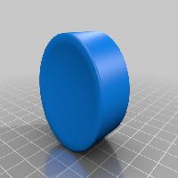
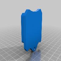
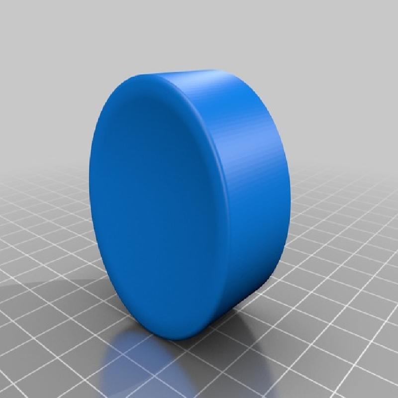
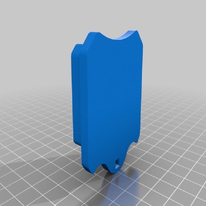
Piston
Print Settings:
.2mm Layer Height
Support at max overhang angle of 45 degrees
Supports from built platform only - Max overhang angle 45 degrees
2 outline/perimeter
30% infill
Printed in PLA (Grey)
Final Thoughts:
For best finish I printed the piston on its side. It seemed to hold its shape well at the end.

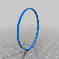
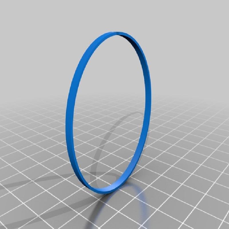
Piston Seal
Print Settings:
.1mm - .2mm Layer Height
1 outline/perimeter
100% infill
Printed in PLA (Orange)
Final Thoughts:
I printed my seals in PLA. ABS should work as well as these will see flexing during installation and removal. PLA will work as long as they are not over bent. It is possible to print these seals with a .5mm nozzle using the settings above. The seal measures a thickness of 1mm.

Brake Pads
Print Settings:
.2mm Layer Height
2 outlines/perimeters
20% infill
Printed in ABS (Red)
Final Thoughts:
The brake pads print pretty easy. You can always reduce infill percent with these.

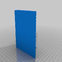
Wear Plates
Print Settings:
.1mm - .2mm Layer Height
1 outline/perimeter
30% infill
Printed in PLA (Black)
Final Thoughts:
Due to the thin nature of the Wear Plates it is best to stick with a single perimeter. I ran 30% infill but this can be increased if you so choose. These do not see much stress or flexing on the caliper
Steps: Post Processing
With the post processing section I will go over areas to focus on with each printed part before assembly. Some massaging is needed to get the parts to fit snugly so they are not falling out of the caliper.
You’ll find below each image, a write up on the areas of focus indicated by the green arrows. Printed items are listed here in order of which you should deal with first to the last.

Piston
Focus Points:
The main areas to focus on with the piston will be the outside diameter as well as the bottom fillet indicated by the bottom right arrow.
I made sure to install the piston in the same direction each time I would take it out and re-install it after sanding. After a round of sanding, try putting the piston back into the bore, if you feel resistance you can pull the piston out again and look at the side of it. The darker grey areas will be the areas needing more sanding.
When fitting the piston, ensure the seal has already been put in place as it will add resistance when inserting the piston and allow you to properly fit the piston.

Piston Seal
Focus Points:
As seen in the above image, the piston seal is split to allow it to be properly inserted as a 3d printed part. A typical caliper would have a 1 piece seal.
The piston seal is pretty easy to post process, keep in mind though that it can be fragile due to its thin wall construction.
The bottom center arrow is indicating the piston seal gap, this may need to be opened slightly with sandpaper so that when the seal is put into the piston bore it fits tight into the groove and both side of the seal should touch each other to appear as a solid seal ring.
The other 2 arrows are showing area’s which may need post processing (Inner and Outer diameters) if you feel protrusions or a lip from the print bed. The seal needs to be smooth to fit well into the groove in the piston bore.

Pad Retainer
Focus Points:
The pad retainer shouldn't need much post processing depending on your printer. If you feel a lip from your print bed on the bottom part of this retainer, as indicated by the green arrows, you’ll want to sand it down.
The top portion of the pad retainer won't need any work as it does not fit into any holes. With this retainer, you will want to make sure it slides into the caliper halves and brake pads with ease. More on that in the Brake Pads and Piston Bore sections.

Brake Pads
Focus Points:
The Brake Pads are another easy post processing print. As indicated by the green arrow, the main area to focus on is the Pad Retainer opening. Be sure your Pad Retainer can slide easily through each of the holes on the Brake Pads. The retainer should not be extremely loose but slide easily through the holes.

Wear Plates
Focus Points:
If your printer does not produce a lip on the print bed side of your Wear Plates then no post processing is needed. If you do feel a lip this will cause an issue fitting your Wear Plates. It is best to run an X-Acto blade to trip off the lip from the edges of the Wear Plates. These edges can be seen by the green arrows.

Bleed Screws & Inlet Fitting
Focus Points:
After you get your Bleed Screws and your Brake Fluid Inlet Fittings from your printer, you will want to make sure they slide into the appropriate holes in the caliper halves. Some resistance when putting the Bleed Screws and Inlet Fitting will be a good thing. You can go ahead and glue in the Bleed Screws and Inlet Fitting if you choose too. They were made to glue in so they would not be lost.
While you're at it, be sure all the holes around the Caliper halves have been sanded out properly especially if supports were used in the holes.

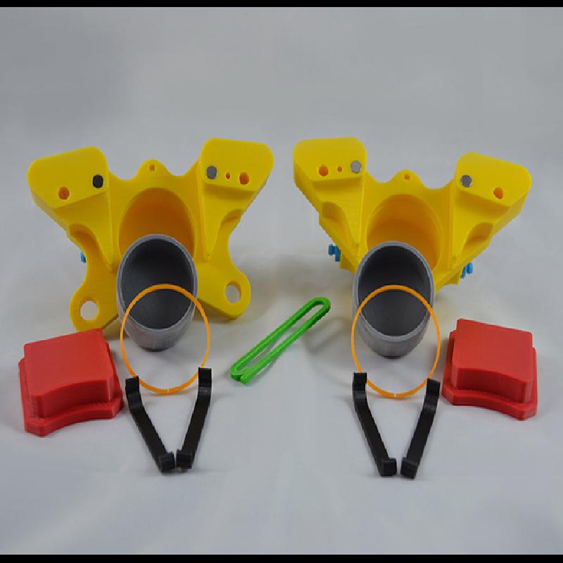
N52 Magnets & Piston Bore
Focus Points:
The magnet pockets should not need much work. Ensure your magnets fit snug into these pockets. You can go ahead and glue in the magnets.
Another area of focus on the caliper halves would be the Pad Retainer hole. It is shown above with the upper center most green arrow. Make sure the Pad Retainer fits easily through this hole on each half of the caliper.
Finally, inspect your piston bores, piston seal grooves and the fluid grooves for any debris from printing. The uppermost groove (furthest from the bottom of the photo) is the piston seal groove and the one of importance. It needs to accept the piston seal in its entirety.
While inspecting the piston bore, ensure the bleed screw fluid passages are clear as well as the crossover port inlet which can also be found in the lower fluid groove. Three holes in total can be seen in the fluid groove and should be checked.
Steps: Assembly
For the assembly, we will look at the process to putting the caliper together. At this point you’ve post processed your 3D printed parts and have probably nearly assembled your caliper already! Congratulations! I will just look at covering some points I used while assembling mine.

Step 1
The first and most obvious of the steps would be to grab your caliper halves. For the graphical representation of the steps I will just be using one side until the final assembly steps. Start off your assembly making sure you have glued in your Magnets, Bleed Screws and the Brake Fluid Inlet Fitting.

Step 2
For Step 2 we will want to insert the Piston Seal into the uppermost groove in the Piston Bore. This is the Piston Seal groove. For consistency, I like to keep the gap/split in the Piston Seal to the top side of the caliper, closer to the Pad Retainer hole. This is optional but it ensures a consistent fit of the Piston in each half.

Step 3
Now we will look at inserting the Piston into the Piston Bore. For consistency like that with the Piston Seal, I have a spot in my Piston that I like to line up with the top of the caliper nearest to the Pad Retainer hole.

Step 4
Next up we will fit 2 Wear Plates to each Caliper half. It is important to make sure each Wear Plate fits properly into the bottom groves as well as the top grooves. If they are not fitting on your model, make sure they are fitting into the groves. If you are still having issues you should refer back to the Post Processing section on pages 12-15 of the included PDF document.

Step 5
Step 5 is pretty simple :) Grab both halves of your caliper. They should look similar to the image above. Each half complete with the Piston Seal, Piston and Wear Plates. You will also notice the Magnets, Bleed Screws and the Brake Fluid Inlet Fitting are already glued in.

Step 6
For Step 6, snap your Caliper halves together and start on Step 7.

Step 7
Start by inserting the Pad Retainer through 1 side of your Brake Caliper. Because this is a model there is no concern on which side you start the Pad Retainer from. You can then slide on 1 Brake pad. Make sure to slide the Brake Pad on in the correct direction as above.

Step 8
For Step 8 you’ll want to continue to slide the Pad Retainer through the Caliper halves. Stop just before getting to the 2nd half of the Caliper and insert the last Brake Pad. After this, you can finish inserting the Pad Retainer the rest of the way through the Caliper. Yours should now look similar to the graphic above. Well done!