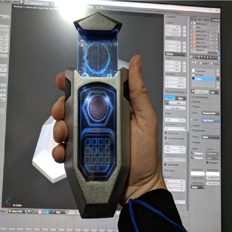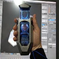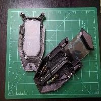
This is a replica of the comscanner prop from "The Orville".
NOTE: This model requires non-printed parts to complete - at the very least, a small sheet of clear polycarbonate or acrylic; however, it's intended to be a functioning hand prop with a spring-loaded scanner screen and LEDs to light both screens. This is not a model you can print, pull off the bed, and display without doing at least some post-printing work and assembly.
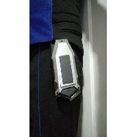
Included in the files are a piece that can be used to make a holster for the comscanner (for cosplay purposes), and a wall-mountable display bracket (designed for use with 3M Command strips).
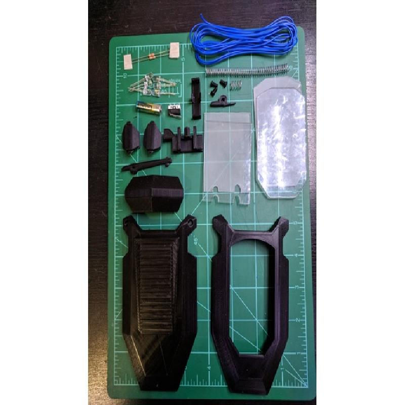
Parts list for a full build:
Small sheet of 0.24mm thick clear polycarbonate (e.g. Lexan) or acrylic (e.g. Plexiglas)
Sheet of laser-printer transparency film (0.11mm thick)
Compression spring, 0.5mm wire, 7.3mm OD, 12mm long
Compression spring, 0.66mm wire, 6.4mm OD, 267mm long (e.g. https://tinyurl.com/y9oast5q)
Six (6) bright white LEDs, 5mm diameter, ~3V, 20mA (e.g. https://www.amazon.com/gp/product/B071GQMLBX/)
1-ohm resistor, 5% tolerance
330-ohm resistor, 5% tolerance
Gikfun Micro Switch, long hinge lever, part #EK1713 (e.g. https://www.amazon.com/gp/product/B015W8S8NA)
A27 battery
Wire
Small sheet of thin copper or brass (to make battery contacts)
Paint, metallic, light (Alclad II Dark Aluminum, Rustoleum Universal Titanium Silver, etc.)
Paint, metallic, dark (Alclad II Steel, Rustoleum Universal Black Stainless Steel, etc.)
Small sheet of black felt (self-adhesive recommended)
Soldering iron
Resin-core solder
2-part clear epoxy, fast-set (e.g. JB Weld ClearWeld)
For holster (optional):
8 Chicago screws (screw rivets), 1/4" length. (e.g. https://www.amazon.com/gp/product/B078V6NB14/)
Leather, 8 to 10 ounce (or synthetic equivalent), 3" by 12"
Belt (e.g. https://www.amazon.com/gp/product/B01N5W7200/)
Threadlock (optional)
Black felt (optional)
Leather punch
For wall mount bracket (optional):
1 pair of medium 3M Command Strips
Printer Brand:
Ultimaker
Printer:
Rafts:
No
Supports:
Yes
Resolution:
0.12mm
Infill:
0.2
Notes:
A raft isn't needed for most of the pieces, but it's strongly recommended when printing the screws.
Support shouldn't be needed for the holster, wall mount bracket, or battery holder, but I recommend it for everything else.
Finishing and Assembly
These are the instructions for creating the full-fledged prop, with spring-loaded scanner screen and lighting. If you're not interested in the hardcore prop-building experience, feel free to eliminate or alter steps as you see fit.
Smoothing
For best results, smooth the outer surfaces of the print by whatever means you prefer (sanding, high-build filler primer, XTC-3D or other self-leveling resin, etc.).
At the bare minimum, if you intend to incorporate the electronics and spring-loaded features, you must sand or file the surfaces of the buttons which will be in contact with the body, so that the print ridges don't catch on each other and prevent them from moving. Also, it's strongly recommended to sand the front edge of the track that the scanner screen carriage slides along. (If you print in the default orientation, the sides of the track need not be sanded unless the carriage is too tight.)
Painting
Paint the exterior of the front and back pieces a light metallic color, such as Alclad II Dark Aluminum (airbrush lacquer) or Rustoleum Universal Titanium Silver (spray can).
Paint the buttons, the cap, and the rounded rectangle on the back piece a dark metallic color, such as Alclad II Steel (airbrush lacquer) or Rustoleum Universal Black Stainless Steel (spray can). Paint the heads of the screws, but not the threads (or just print them in black and don't paint them).
Allow all paint to fully dry (otherwise the buttons may stick). If you do have problems with sticky buttons, spray a little silicone lubricant into a baggie, and use a Q-tip or paintbrush to put the lubricant onto the surfaces of the buttons that slide against the interior of the main body.
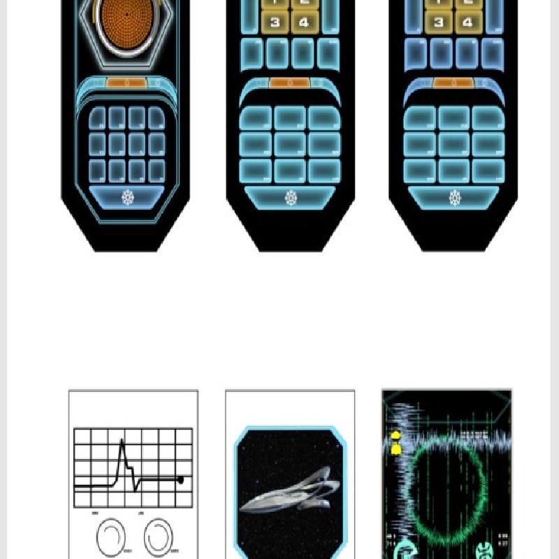
The Screens
Comscanner Screen.pdf should be laserprinted on a transparency sheet (0.11mm thickness). It contains three variants for each screen, based on screencaps from the show; cut out the desired version for each screen.
If you don't intend to put the electronics into the model, printing it on bright white paper may be a better option.
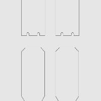
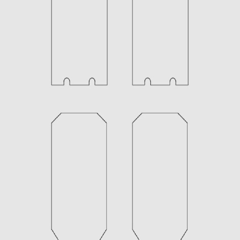
Print Comscanner Screen Templates.pdf, use this to cut out four pieces of 2.4mm thick clear polycarbonate (e.g. Lexan) or acrylic (e.g. Plexiglas). Just cut the rectangular pieces as straight rectangles, ignoring the rounded bits for now.
Evenly spread clear epoxy on one surface of each polycarbonate/acrylic piece, and sandwich the graphics between them. Clamp well and wipe excess from the sides. Allow to dry.
If you intend to include the electronics: leaving the rectangular group clamped, drill out the rounded bits (LEDs will be inserted into these spaces).
Sand the long edges of the rectangular screen so that it's smooth, and has slightly rounded corners.
Using clear epoxy, glue the com screen (the elongated octagonal one) into place.
Epoxy the cap onto the top of the scanner screen (the rectangular one), and the carriage onto the bottom. Make sure the holes in the carriage line up with the drilled holes in the screen, and that the cylindrical extension is on the back of the screen. (The latching portion should be on the left side.)
Allow to dry.
Felt
Cut two rectangles of felt, sized to match the inside top edge of the front and back of the body, making sure it doesn't extend past the edge of the piece. Adhere the felt pieces there. (This is to cushion the scanner screen when it pops up.)
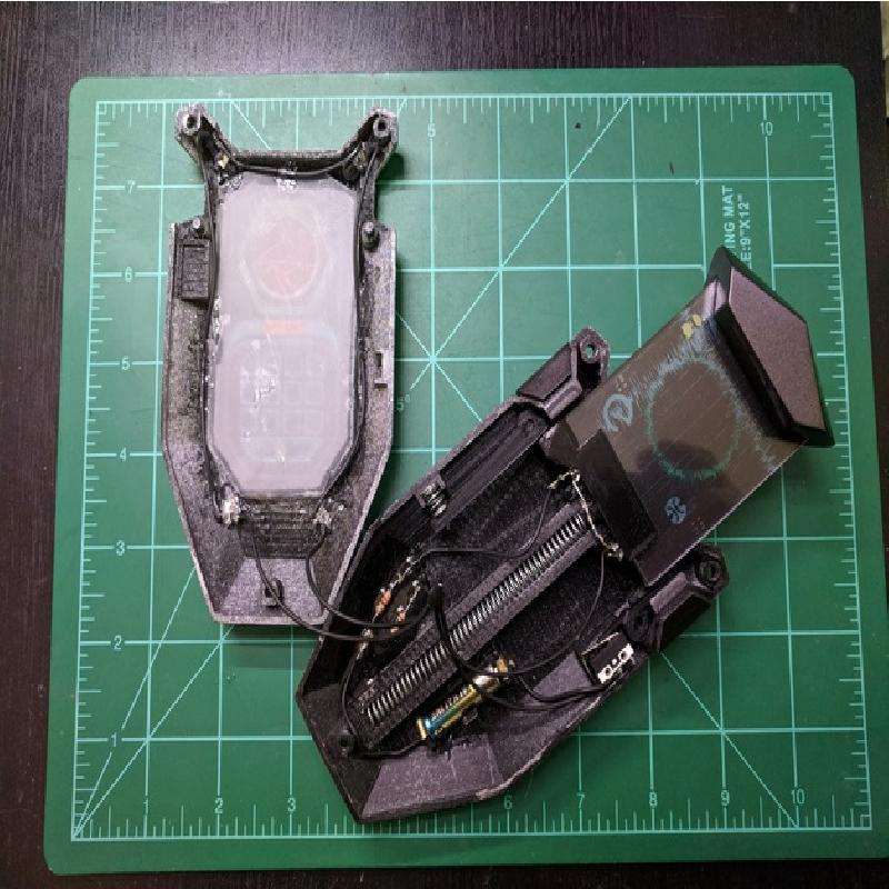
Springs
Cut the long spring to 90mm (3.5 inches). Slide it into the carriage track from the top. Insert the cylindrical projection on the back of the carriage into the top of the track. Test to make sure it slides freely; if not, sand the track until it does.
To save yourself a lot of headaches, epoxy the small spring into the receptacle about halfway down the left side of the back piece. It should be oriented horizontally.
(Refer to the full-sized image in Comscanner Interior.jpg.zip, if any of this is unclear.)
Switch
On the right side of the back piece, just below the button cutout, you will find a rectangular area. Place the switch on its side within the rectangle, with the lever hinge at the top left, and trim the contacts slightly so that they don't intersect with the right wall of the body.
With the switch in the same orientation, solder wires to the top and middle contacts, arranged so that they travel down alongside the contacts (one in front of them, one behind them).
Epoxy the switch into place on the back piece. Clamp well; allow to dry.
(Refer to the full-sized image in Comscanner Interior.jpg.zip, if any of this is unclear.)
Battery Holder
Cut out two small rectangles of copper or brass. Solder one of the wires from the switch to one end of one rectangle; solder a new wire to one end of the other. Fold rectangles over the top and bottom projections on the battery holder (with the wires on the outside). Epoxy into place, making sure not to get any epoxy on the inside of the terminals, where they will be touching the battery.
There is a small rectangular depression on the right side of the track, below the centerline of the back piece. Epoxy the battery holder into this spot, with the end connected to the switch towards the top. Allow to dry.
(Refer to the full-sized image in Comscanner Interior.jpg.zip, if any of this is unclear.)
LEDs
Place two of the LEDs into the holes on the bottom side of the carriage, so that the negative lead is on the left of each LED, and the positive lead on the right. Bend the innermost leads so that they're lying alongside each other, leaving a little space in front of the carriage track. With a felt-tip pen, mark the leads so you can solder them into that position. Remove the LEDs. Solder the leads. Clip the other leads short and solder wires to them. Reinsert them into the carriage and epoxy into place.
Arrange the other four LEDs in the corners of the com screen on the front, aimed at the center of the screen. Clip the leads short. Cut wires of the appropriate lengths, and wire them into a series going from one bottom corner, around the top, and back down to the other corner. Epoxy the LEDs into place. If you epoxy the wires down, to keep them out of the way of the carriage, make sure they're left free in the area of the button cutouts.
Solder the two resistors to the wire coming off the bottom (negative) terminal of the battery connector. Solder the other end of the 1-ohm resistor to the negative wire of the four front LEDs, and the other end of the 330-ohm resistor to the negative wire of the two carriage LEDs.
Solder the free wire coming off the switch to the wires coming from the positive leads of the LEDs.
Epoxy the resistors onto the left side of the back piece to keep them separated, wedging the wire leading to the battery holder between the track and the bottom screw post.
Insert the A27 battery into the battery holder, with the positive terminal towards the top. Press the switch lever to test.
(Refer to the full-sized image in Comscanner Interior.jpg.zip, if any of this is unclear.)
Levers and Buttons
Place the short 3D-printed lever on the post above the switch (right side of the back piece, just below the button cutout), with the larger arm upwards and the smaller arm alongside the lever on the switch. The arms should be to the left of the post.
Place the long 3D-printed lever ("Latch") on the post below the left button cutout, with the long arm downwards, and the arms on the right end of the post. The round protuberance on the long arm should fit into the spring, and the pointy protuberance should be pointing inwards.
Push down the carriage and ensure that it latches. Press on the lever to release it (hold onto the carriage to make sure it doesn't release with enough force to jar the levers free).
Slide the buttons in, taking care not to dislodge the levers. The top edge of the buttons are not completely straight (and there's a little dot on the inside, above the main post that contacts the levers, to indicate which end is the top).
Assemble
Put the front half on. Because of the LED wires on the front half, you'll have to do some maneuvering to get around the buttons. Snap into place.
Screw in the three screws. Although they're modeled as Philips screws, I've found that a small slotted screwdriver works better to avoid stripping the drive.
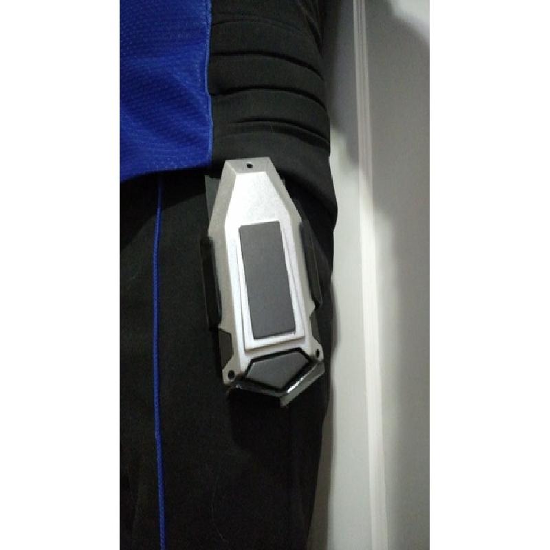
Holster (optional)
If you want to make a holster for the comscanner, for cosplay purposes, print the holster piece. Smooth, paint gloss black.
Cut off the bottom of the leather strip to match the angles of the bottom of the holster. Mark and punch four holes at the bottom of the leather, matching the holes in the back wall of the holster.
Using four Chicago screws, affix the holster to the leather strip. Use Threadlock, if desired.
Punch four holes at the top of the leather strap, matching the spacing of the holes on the belt. Use the other four Chicago screws to affix the leather strap to the belt.
I strongly recommend lining the interior of the holster with thin felt, to avoid scratching the comscanner.
Wall display bracket (optional)
Affix one 3M Command Strip to the back of the bracket, centered, with the square short edge of the strip flush with the bottom edge of the bracket. Click the other strip onto it, remove backing, place on wall. Allow to set.
Place comscanner into bracket. Admire the fruits of your labor.
Modeled in Blender, based on various screenshots from the show.
I can't guarantee that the size is accurate. I measured the ratio of the button to the distal phalanx of Seth MacFarlane's thumb in a close-up shot of the comscanner, calculated the same ratio using my thumb's measurement, and scaled the result up by about 3% since MacFarlane is slightly taller than I am.