

by Acid44
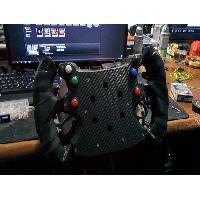
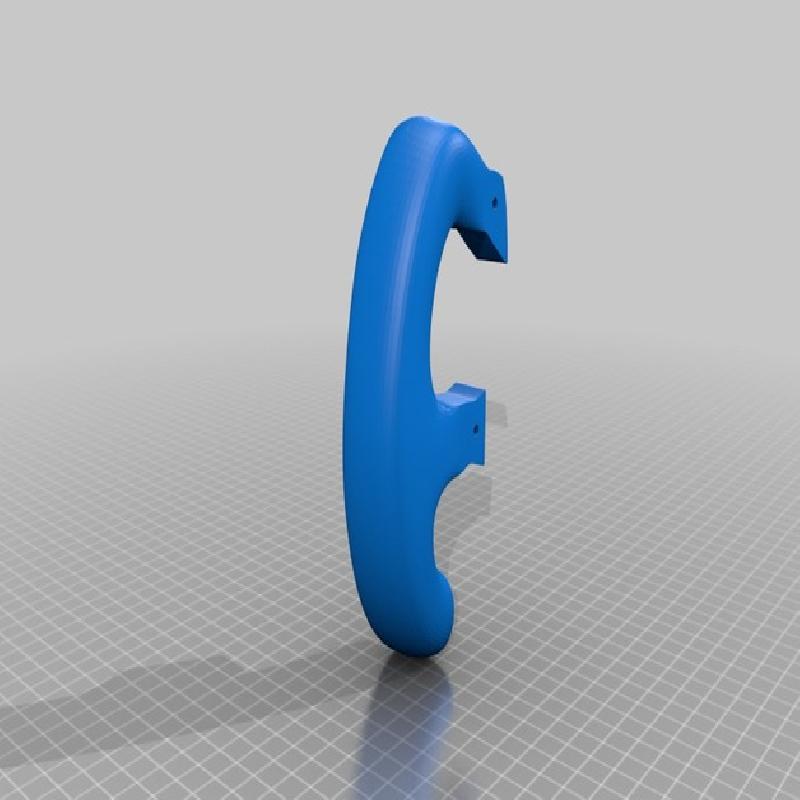
Been working on this one for a while now. A Formula 1 style steering wheel designed specifically for my Logitech G27 with 70mm adapter. I'll try my best to outline everything you need to know to print and use this, at least for the G27. If I miss anything just leave a comment to ask.
Wiring doesn't take much, but I've put some details below you help you along.
For assembly you'll need some M3 screws and nuts. I used M3x35, but I think 30mm might work too. The 35s stick out the back a bit.
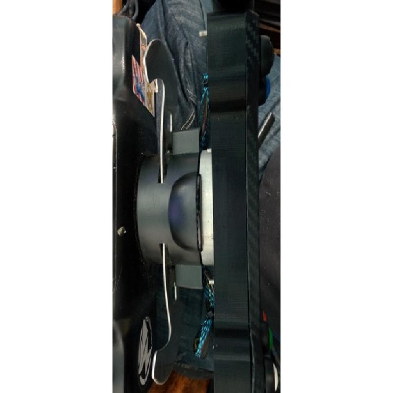
You'll also need a 70mm adapter if you're using this with a G27, there's a few on here, so just pick one, or get a machined aluminium one from eBay.
The grips are ok as they are, but I have giant lanky hands, so I wrapped them in bicycle handlebar grip tape stuff. There's tons out there, in all sorts of colours, so go nuts.
EDIT: Updated to STL, so the Thingiviews should work now.
Rafts:
No
Supports:
Yes
Resolution:
0.2mm
Infill:
10-20%
Notes:
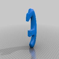
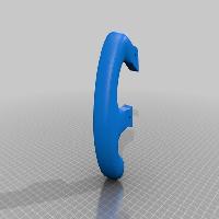
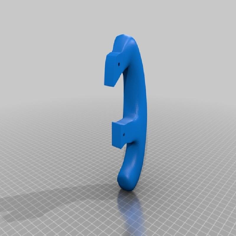
Grips: I found it best to print the grips at the same time, rather than separately. I think it's just because I have bad cooling at the moment, so with just one printing the curves and overhangs were a bit difficult. With two printing it gave me more layer time so things could naturally cool.
Lay both grips down so their backs are on the bed as shown here: https://imgur.com/a/7yw9k5m
Use some tight supports, they'll vary but you really don't want droopy bits stabbing your fingers.
I used 10% supports at 0 and 90 angles with 2 dense support layers @70% in Simplify3d, and 15% fast honeycomb infill
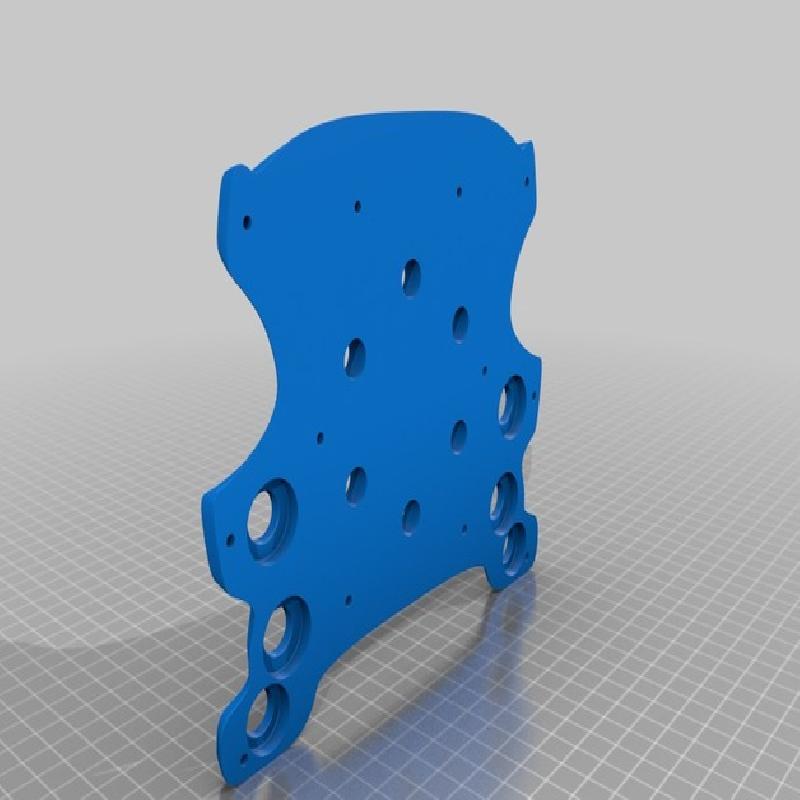
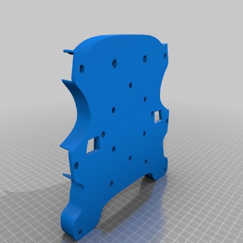
Face: Pretty simple, just lay it down so its back is on the bed, use some supports so the button areas come out well, and that's really it.
Optionally stop the print a layer early, or set it to stop printing at like 0.3mm under the height of the model. I couldn't get the top as flat as I wanted. The joys of doing stuff like this in Maya instead of a proper CAD software.
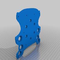
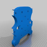
Back: Just lay it down on its back, and use sufficient infill. I used 20%, and added an extra layer of wall thickness all around.
Wiring
What you need:
Micro JST 2.0 PH 4-Pin connectors, like these: https://www.amazon.com/Micro-Connector-150mm-Cable-Female/dp/B01DUC1S7S
12mm buttons, like these: https://www.amazon.com/Cylewet-Self-locking-Latching-Button-CYT1091/dp/B075VBV4QH/ref=sr_1_7?ie=UTF8&qid=1532795167&sr=8-7&keywords=12mm+button
Soldering stuff
Optional: small cable sleeves, cant remember exactly what size I used, but I believe it was 3/8 inch
Soldering:
When the buttons are in, you'll need to chain ONE connector from each button together for each side. These are basically the grounds. These will go to the black wire of the JST connectors. So each black wire should have 3 buttons chain connected to it basically.
The others are your signals. If I recall correctly it goes red, white, yellow, from top to bottom, but I may have that backwards.
So, something like this embarrassing MSpaint work: https://i.imgur.com/xuqy0Uy.png
With these connectors, it will plug directly into the G27 base, replacing the default buttons. You might want to remove the little PCB that these plug into from its standoffs to plug them in, as the female ends of the connectors can be a bit weak/finnicky.


