by Shipbrook
Important Note: This is just the Phaser II body; it does not include the Phaser I, which is available as a separate model.
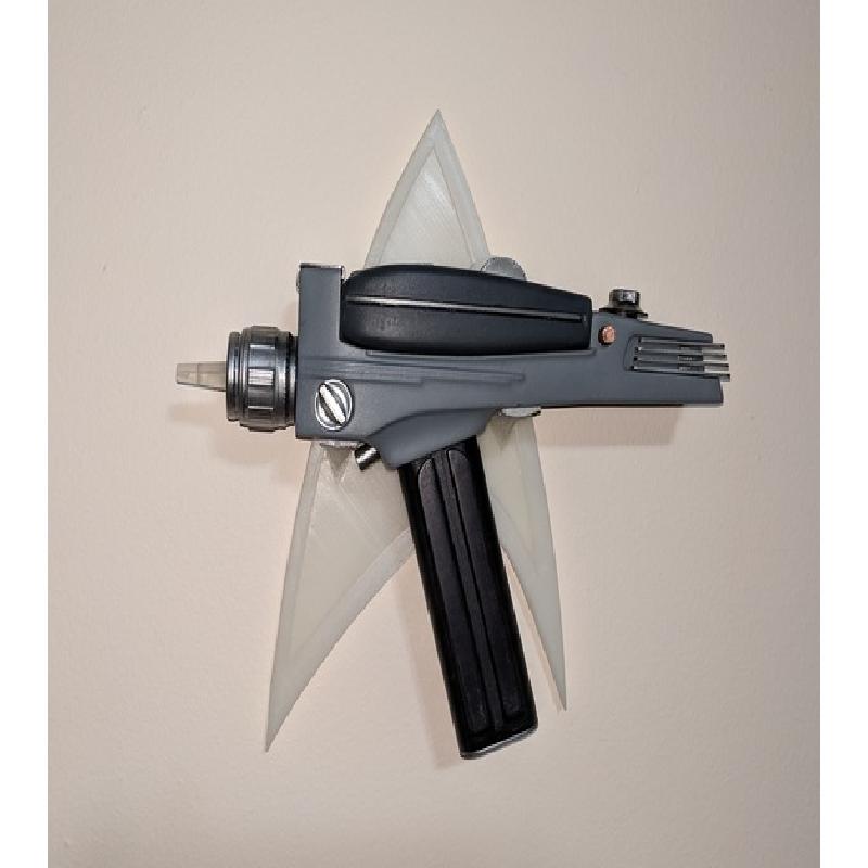
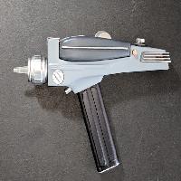
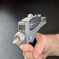
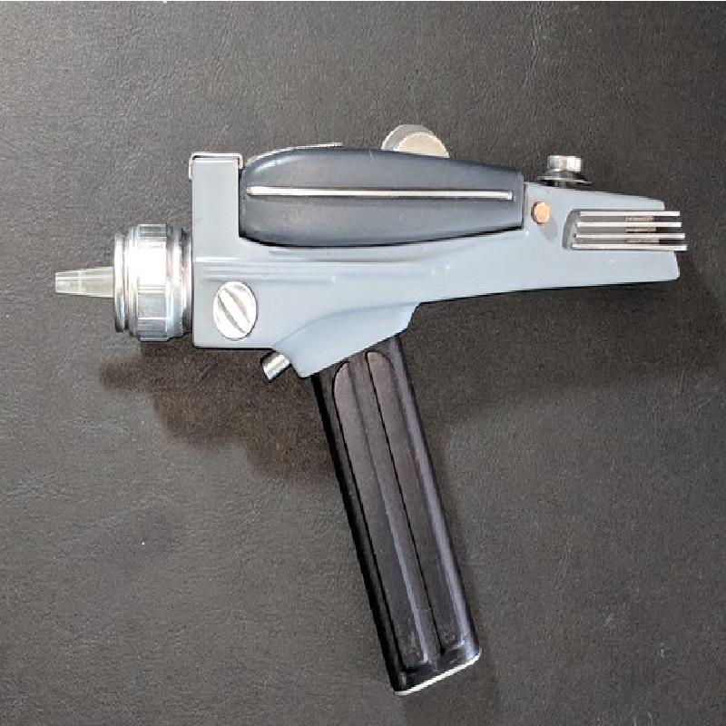
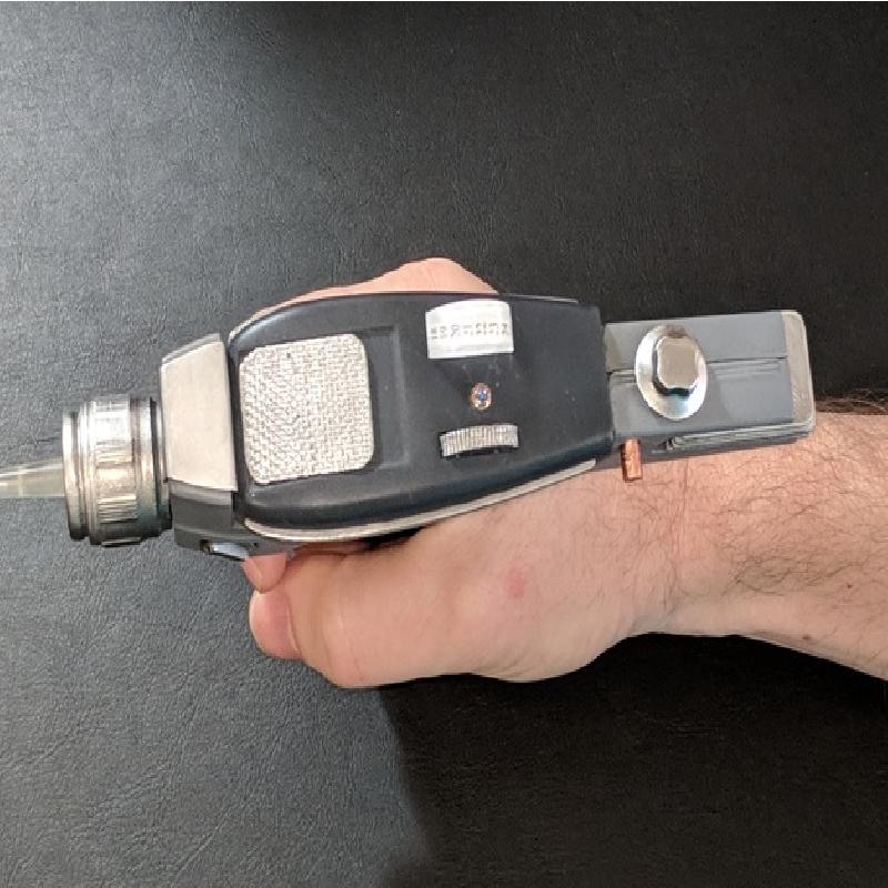
This is a midgrade version of the Phaser II pistol from the original Star Trek series. It has a working latch to retain the Phaser I, but apart from that the knobs and trigger aren't made to be functional.
The model is split into multiple sections for best printing results, and for ease of painting. Some assembly is required. (Okay, a lot of assembly is required.) Some parts which make a single unit ("Ten Turn" knob, side knob, rear fins) are models which contain separate parts.
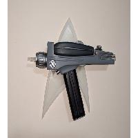
Two optional wall plaques are included (for displaying the phaser pointing in either direction), designed to be affixed to the wall with 3M Command Strips.
Additional Note: I call this one "Midgrade" because it's mostly nonfunctional, but design-wise it more closely resembles the hero P2 (separate rear fins, ten-turn knob, etc.). I'll eventually be adding the early first season version, which was repainted and slightly updated for use as the actual midgrade P2 body.
Printer Brand:
Ultimaker
Printer:
Rafts:
No
Supports:
Yes
Resolution:
0.12mm
Infill:
15%
Notes:
If you plan on painting the model after printing (smoothing first is highly recommended!), the filament color is unimportant except for the emitter and window, which should be printed in clear or natural (and definitely smoothed using successively finer grits of sandpaper). If you simply want to print in "close enough" colors, I recommend:
Body left and right halves: light grey to medium grey. (The screen-used props were repainted from time to time, and the colors were not entirely consistent.)
Fin block, front clip, nozzle, power pack end cover plate, rear fins, trigger, ten turn knob, side knob: silver
Power pack, power pack end: black
Emitter, window: clear or natural (If you smooth nothing else, smooth these pieces with successively finer grits of sandpaper. Aesthetics aside, the window won't slide into the body unless it's smoothed!)
Release button: copper
Other parts: any desired color
1. Pre-Painting Assembly
Glue the Power Pack End onto the Power Pack (but don't glue the end plate on yet).
Glue the parts of the "ten turn" knob together. When placed in the cutout on the body, it should turn freely.
Note: here, and throughout these instructions, where I say "glue" I used two-part clear epoxy.
2. Finish Parts
If you're going to paint the model, I highly recommend smoothing the exterior surfaces of the parts.
I used Smooth-On XTC-3D, then sanded away any imperfections that remained using progressively finer grits (120, 220, 320, 600, 800, 1000, 1500, 2000).
3. Prime
I used "Alclad II Grey Primer and Microfiller" on all parts except for the emitter and the front window.
4. Paint
To get a nice smooth surface, I recommend using an airbrush.
For the body halves, I used Vallejo Neutral Grey, followed by a coat of Alclad Klear Kote Light Sheen.
For the fin block, front clip, nozzle, power pack end cover plate, rear fins, trigger, ten turn knob, and side knob, I covered them first with Alclad II Gloss Black, then painted with Alclad II Airframe Aluminum, and finally coated with Alclad Klear Kote Gloss.
The release button was painted first with Alclad II Gloss Black, then covered with Model Master Copper, and coated with Alclad Klear Kote Gloss..
I painted the power pack with Alclad II Steel (and the slotted nut on the bottom with Model Master brass). Then coated it with Alclad Klear Kote Light Sheen.
5. Post-Painting Assembly
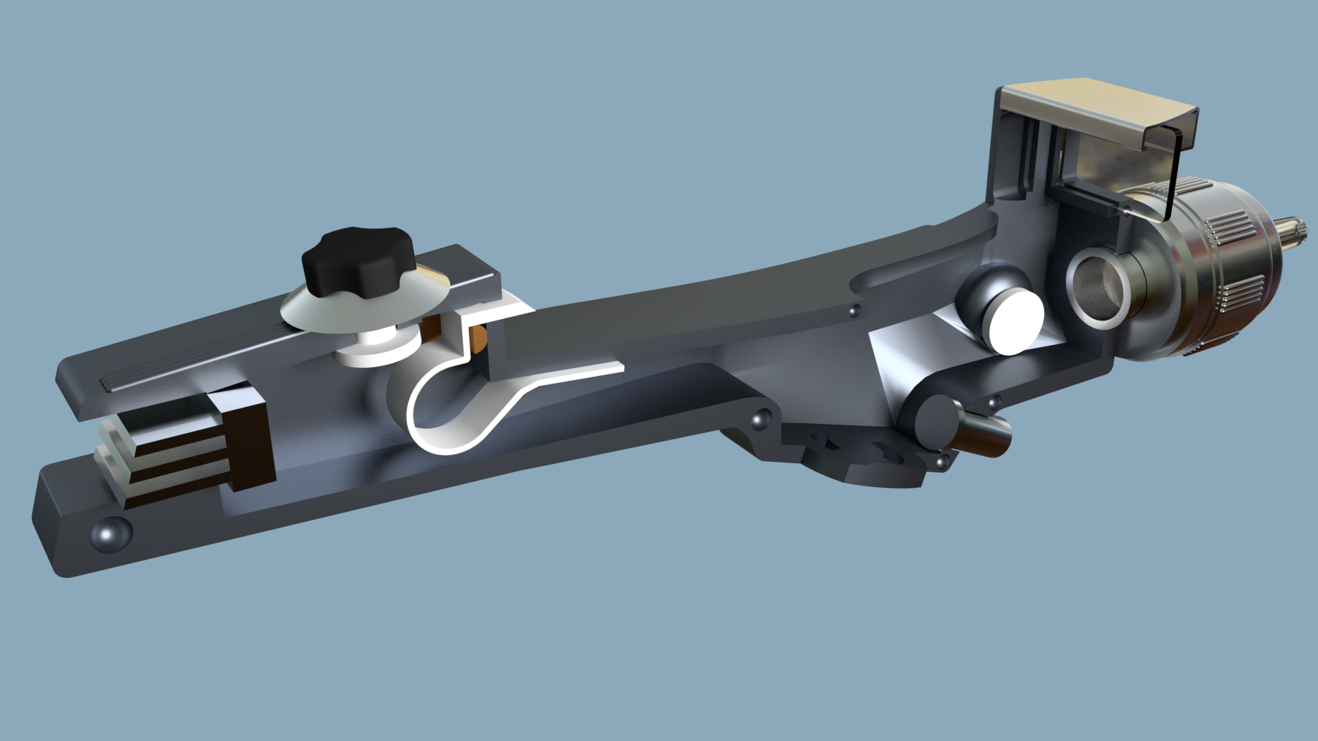
Insert the release button through the hole in the left half of the body, anterior to the P1 cutout, rotated so that the half-cylinder is forward. Glue the latch spring in place as shown in the assembly diagram (below). The side edge of the latch spring will overlap the edge of the body.
Glue the power pack end cover plate to the bottom of the power pack.
Put glue around the wide base of the emitter. Holding the nozzle so that the front end is downward, carefully drop the emitter through the rear hole so that it pokes out through the front hole. Adjust the emitter so that it's centered, and allow to dry. (I let it rest on a couple of popsicle sticks laid across the top of a cup.)
Once that's dry, you can glue the nozzle retainer into the rear of the nozzle. Adjust it so that the nozzle is held flush against the front edge of the body, but can still turn if desired. Allow to dry.
Either glue the side knob into the recess towards the front of the left body half, or glue it to the small post that's part of the model to allow it to turn (some sanding to fit might be required; be sure not to glue either part to the body).
Glue the fin block into the notch in the rear end of the left body. The shortest "ledge" should be at the top, and the solid part should be flush with the edge of the body. See the assembly diagram below.
Glue the trigger into the left body.
Glue the front clip onto the left body. The wide end should be at the rear, and the narrow end at the front.
Once everything is dry, slide the front window into the slots in front (above the nozzle and below the clip). Slide the ten-turn knob and the nozzle into place.
Carefully glue the right half onto the left half. A number of registration keys are modeled into the edges to help you keep them aligned.
Glue the rear fins into place. Each one is a different length; the shortest one goes on top, the longest one on the bottom. It can be a little tricky to get them straight.
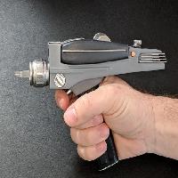
Finally, once everything's dry, insert the power pack (handle) into the slots on the bottom, and twist until it's straight. (I'll be honest, the tabs can be kind of flimsy, so you might want to just epoxy it into place.)
To insert the Phaser I, put the front end into the space under the front clip of the P2 body, then snap the rear end down into place. The latch spring should catch in the slot at the rear of the P1. To remove the P1, just turn the release button until the latch pulls back far enough to let the P1 lift out.
(Yeah, okay, perhaps I should have called it the release knob. I'd originally intended it to push in to release the P1, but couldn't find an efficient way of doing it.)
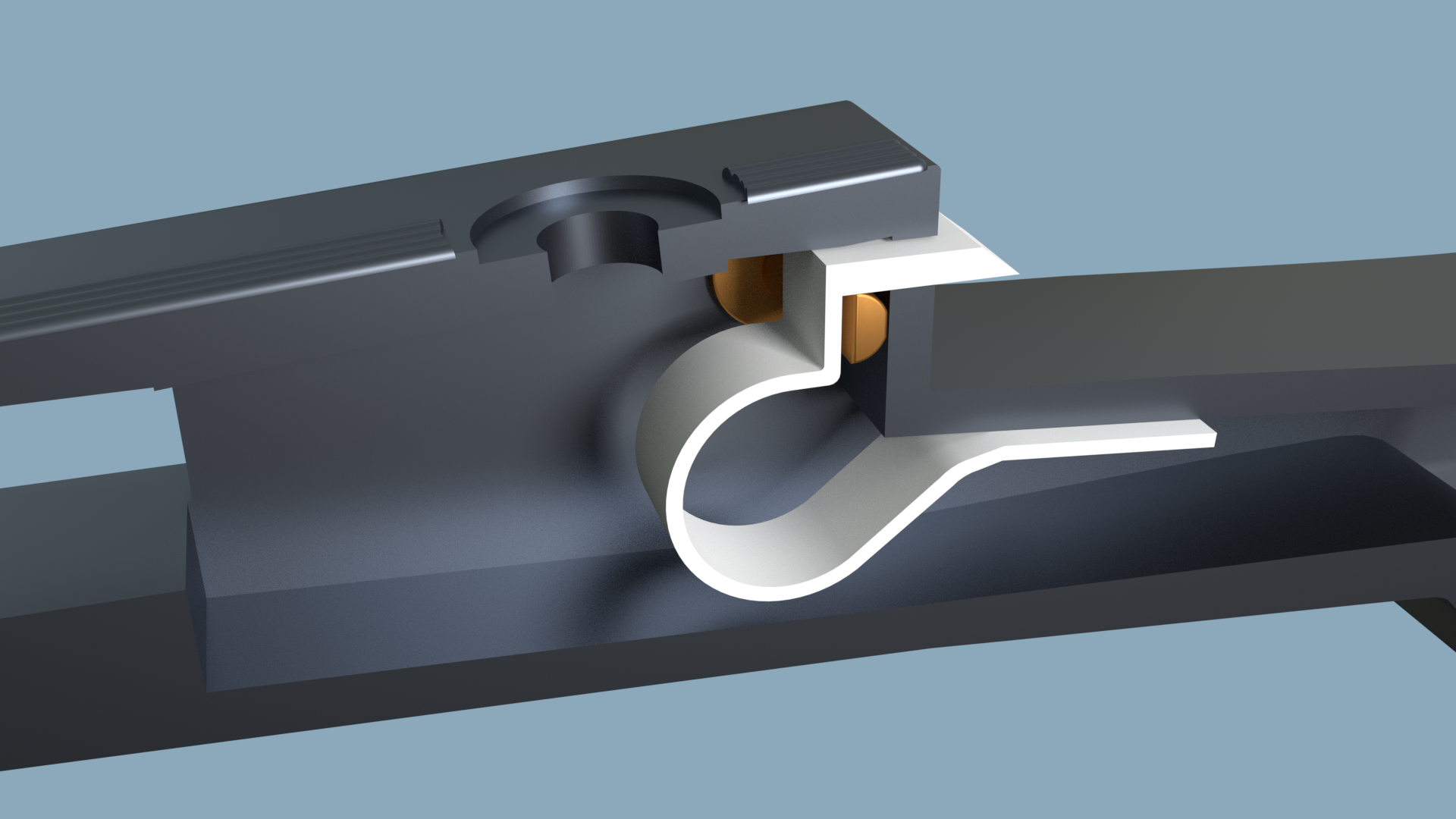
Assembly diagram: release button and latch spring
Assembly diagram: knobs and such
Modeled in Blender, working from numerous screen shots of the props from the show.