by BigTendies
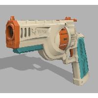
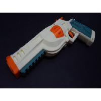
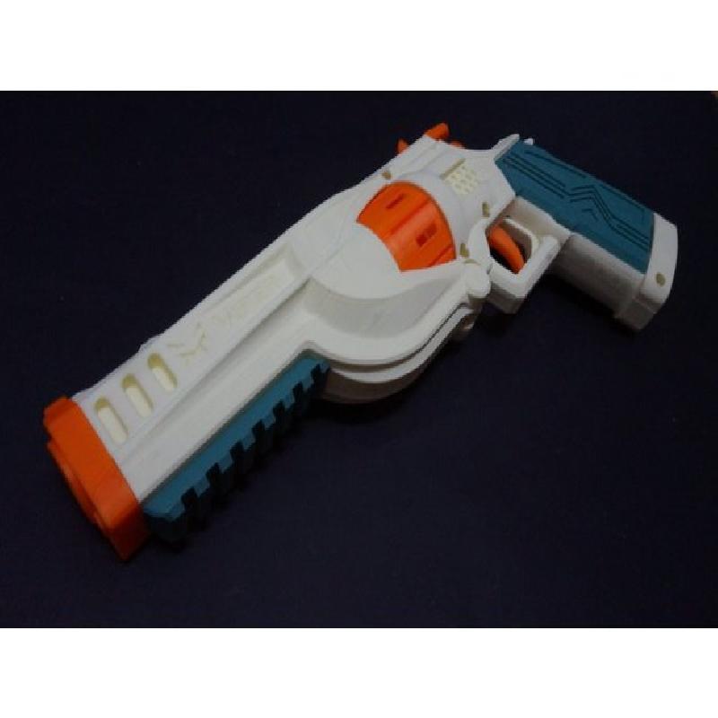
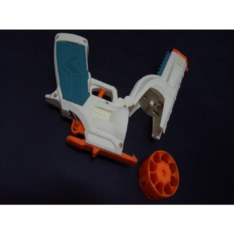
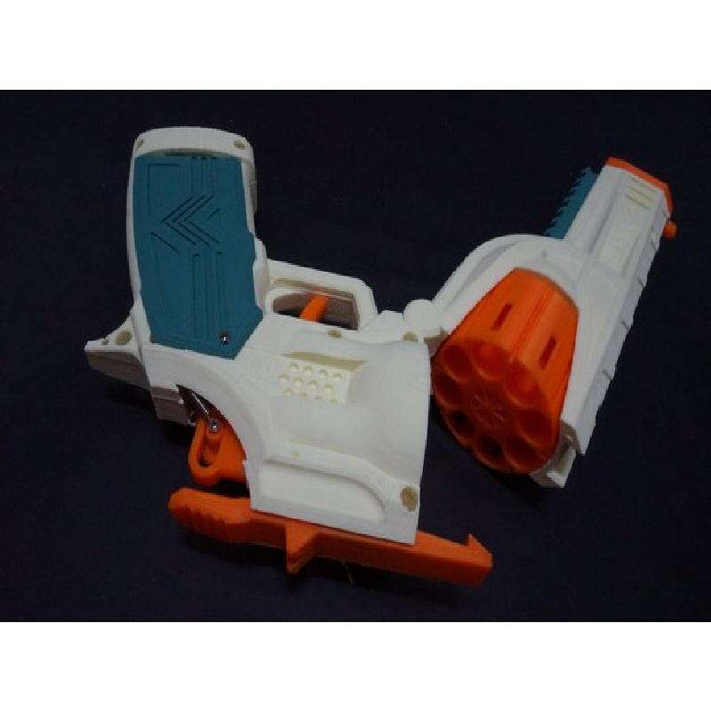
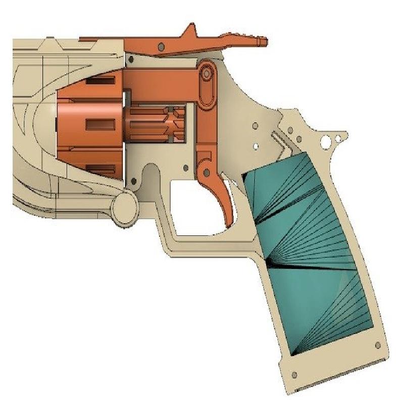
The Freedom Blasters FR-1 Viper is a compact semi auto revolver that uses the FTW flywheel system. Its drum can store 8 short darts and it can be reloaded by either opening the break and inserting darts into the drum manually or swapping the drum entirely. Serves great as a secondary or primary on HvZ due to its flexible reloading capabilities. Build instructions and hardware list is written below.
Please follow the build instructions carefully as this is a rather short but complex build.
If you want to buy the blaster completed and assembled, it will be VERY soon available on the Flywheel the World store. When that happens, I will drop a link here.
Feedback is very much welcome and though I might not be able to respond to everyone, I read everything. If you run into issues, I'll do my best to help. Also, before anyone asks, a full length dart version is planned right after I'm confident that the core design works without major flaws.
I should also note that selling the blaster without permission is illegal. If you are a seller interested in selling and manufacturing Vipers, please contact me directly.
Printer Brand:
TEVO
Printer:
Rafts:
No
Supports:
Yes
Resolution:
0.21-0.24
Infill:
20%
Filament: Gembird PLA Literally any
Notes:
Freedom Blasters Viper printing and assembly instructions.
Warning: the build requires some experience in building blasters, so it's not the best first build.
Parts list:
Soldering iron, other obvious nonsense;
Motors: Honeybadgers get you 110 on 2s and 130 on 3s and Meishels give you 80 on 2s. Would appreciate more data in the comments if you try a setup not mentioned here;
Appropriate battery. The tray can support a battery that is about 70x35x17mm in size and since it's not exactly box shaped you could probably tuck the wires to the side quite easily;
Micro flywheels of choice;
Some wiring that isn't needlessly thick You can check the AWG you really need by looking it up. PC insulation works great here as it doesn't rub on the hinge and is cheaper;
Heatshrink;
An Omron switch;
3mm pin material or its nearest imperial equivalent;
Regular Nerf screws but for the best results, use M2.5 or M2.6 flat top Philips head self tapping 10mm long screws. The screw that holds the switch needs to be a bit longer. You will need about 15;
Two motor screws. Yes, only two;
An extension spring and a compression spring. The extension spring needs to be pretty stiff but no higher than 5mm in diameter. I've used 4x0.4mm spring material. The compression spring should be medium to hard stiffness. You will need two if you want to use an assist spring, otherwise only one.
Battery plug of choice.
Optionally, some barrel material. For that, you will need some painting or electrical tape as well.
Printing instructions:
Note that the parts aren't always oriented in the best way to print.
At most 0.25 layer height, 0.20 recommended. For the cam, use 0.15-0.10 for the best results.
Use no less than 3 wall perimeters.
Parts are originally meant to be printed flat, but people have had success printing them at 45 degrees. Do whichever works best for you, but make sure you aren't creating weak points, especially in the nose hinge-cage bottom linkage. That means, you should NEVER print the nose bottom vertically.
Make sure your layers aren't "mushed" to the build plate too hard - if you lose bottom layers you might end up with some friction in the mechanism and you certainly don't want any of that in this build.
Tree supports do wonders on this build but use whichever you prefer.
S3D tends to mess its tolerances up (it is all adjusted for Cura) by shrinking overall perimeters by about 0.25, so you might want to adjust your Horizontal Expansion setting accordingly. Or, simply use Cura.
The total print time as about 20 hours on recommended settings.
Picatinny rail is optional.
Assembly:
1) The assembly process begins with the nose bottom. Before proceeding, test fit the motors. If you printed everything right, they should fit without much resistance. Otherwise, try sanding. Find the right orientation for your motors. Run positive and negative wire through the long wire channel on the bottom of the part. Solder on the motors. They need to be soldered on very well because if a messup happens, you'll need to remove a lot of parts to get to them again. Then, slot in the motors while slowly pulling the wire through the channel. Make sure the motors rest against the bottom or something might break when pressing the flywheels in. Never happened to me but it could in theory.
2) Screw in the motors with one screw each and press in and screw on the motor cover. It should press against the motors but not pop out from the surface or it will interfere with the drum.
3) Press in the flywheels on the motor shafts. Use the flywheel tool to make sure you don't press the min too far or anything else that can leave 1.5mm of space. Take your time aligning them.
4) Take the Right shell piece and slot it into the hinge on the nose. Cut the pin to length and slot it into the hole. Make sure the wires fall into the slots properly.
5) Place the pusher, cam and trigger into place. The pusher is a snap fit. Its tooth also needs to be nicely sanded into a smooth trapezoidal profile. Screw the cam in, but don't tighten it completely. In fact, leaving a visible gap is totally fine. Place the extension spring - one end on the top of the trigger, the other - on the top left hole on the very right. I needed to cut it to lengths of about 18 mm but go higher and cut down if needed. You can use a compression assist spring if there is too much friction anyway, but I haven't tried that technique out myself yet. Don't forget to cut to length and place the trigger pin.
6) Solder the switch on one of the wires. Keep in mind that the switch is inverted (electricity flows when it's NOT pressed) and the end that goes to the battery.
7) Add the battery plug. Don't forget heatshrink. You can test the system if you want to.
8) Assemble the break lock. It uses a far shorter pin and has a compression spring slotted inside.
9) Screw on the left shell piece. Make sure the break lock assembly doesn't fly away and if it doesn't want to close completely some of the pins might be too long.
10) Screw on the right grip. You might need to clip the screw to length so that it doesn't run into the switch. Insert the battery and close it with the left grip panel.
11) Take the nose top and slot in the tip. Screw the assembly onto the bottom of the nose with four screws - two on top, other two on the tip.
12) Add the picatinny rail if you want.
13) Test the break action. If it doesn't quite lock, you might need to sand the tooth down a bit until it locks. Try not to overdo it.
14) Test fit the drum. It MUST rotate completely freely then the break is closed, otherwise the spring will be unable to return the pusher back. If it doesn't you might need to sand interferences off. This step caused the most issues for most testers. It's always best to adapt the blaster rather than the drum.
15) If you want to use barrel material, wind some tape on it until it can firmly friction-fit inside the blaster.
16) All done!