by mechanic403
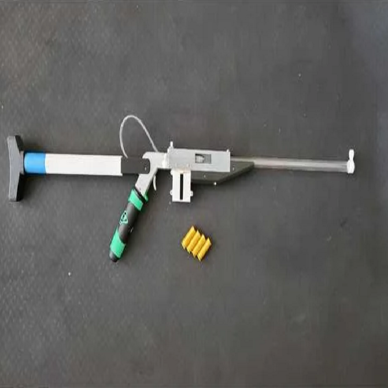
An Air Rifle that shoots 1 inch blow darts powered by CO2. Magazine fed with shell ejection mechanism
DISCLAIMER: By downloading these files, you agree that I shall not be liable for any damage, injury or harm resulting directly or indirectly from the use of these files or instructions. Always be safe and aware when operating these mechanical toys and enjoy!
16g or 20g threaded CO2 canisters
Neodymium cylinder magnets (5mm Dia, 3mm Height) [x8]
PVC Pipe (1in Outer Diameter 3/4in Inner Diameter)
M4x20 screws [x2]
M3x30 screw [x1]
M3x20 screws [x6]
M2x16 screws and nuts [x4]
M2x10 screws [x2]
Small and medium rubber bands
Ive included two variants of the shell depending on your printer's tolerance / filament. One has a 10.1mm inner diameter for a tight fit with the darts, and the other has a 10.3mm inner diameter for a somewhat looser fit. The darts should be pretty tight when inserted such that they dont fall out when tipped upsidedown, but not so tight that they cant be pushed out. Try printing one of each shell to see which works best for you. You can do finer adjustments to the tolerance by putting some scotch tape or masking tape on the inside of the shell wall.
Print the shells with the flat bottom on the build plate at 0.3mm layer height. You might want to add a 2 or 3 mm brim to keep them attached to the build plate. If so, ensure you cut off the brim with a knife so there is no extra flashing as this will prevent them from being properly ejected.
Gather the two magazine halves, the MagazineShellLift, a rubber band, 4 Neodymium magnets and 4 M2x16 screws and nuts.
First, push the magnets into the holes on either side of the magazine. Ensure their polarity is consistent; the magnets on either side should have their North pole facing outward.
Sand down the inner faces of the magazine halves so that they can be placed together without gaps. Place the MagazineShellLift between the two halves with the small tabs in either slot of the magazine halves. Connect the two halves together, enclosing the lift, then secure with the 4 screws and nuts. Ensure the screw heads are fully inserted so the sides of the magazine are flat and the heads do not protrude. Loop the rubberband around the top of the magazine, above the two screw brackets, then bring the band underneath the two tabs of the Lift.
Gather ReceiverTop, ReceiverBottom, ShellEjectorCam, the ForeGrip halves, RearSight, a small rubber band, 4 magnets, 8 M3x20 screws, 2 M2x10 screws.
Press the 4 magnets into the holes on the sides of ReceiverBottom, ensuring that the polarity of the magnets is such that they attract the magnets on the magazine when the mag is inserted into the magazine well on the bottom Receiver.
Sand down the top face of ReceiverBottom and the bottom face of ReceiverTop such that they can be placed together without gaps.
Take the ShellEjectorCam and use an M2x10 screw to secure it to the rear hole in the small recessed slot on the left side of ReceiverBottom. The Cam's hook should protrude slightly out of the left side. Ensure it can rotate freely around the screw. Next, screw in the other M2x10 screw into the hole in front of the cam. Dont screw it in all the way, leave enough room to loop a rubberband around that screw and connect it to the hook on the ShellEjectorCam.
Next, connect ReceiverTop and Bottom with 4 M3x20 screws using the front and rear most pair of holes.
Now take the two ForeGrip halves and screw them together with 2 M3x20 screws through the holes on the left side of the ForeGrip. Attach the ForeGrip to ReceiverBottom via two more M3x20 screws through the bottom of the ForeGrip going through the pair of holes second from the front of ReceiverBottom.
Take your rigid tube for the barrel and cut it to your desired length. Apply a small amount of hot glue to the edge of the tube and quickly press it into the front of the Receiver such that the glue forms a seal.
Finally, take the rear sight and glue it to the top of ReceiverTop, mating the small tab into the slot on the Receiver. Take the FrontSight and place the ring around the tip of the barrel.
Gather the BoltSlider, the BoltLeverArm and BoltExtractorArm.
Depending on how you printed the BoltSlider (split halves or single peice with supports), clean it up and connect the halves with glue if necessary. Sand it down as so it is as smooth as possible and can slide and rotate freely into the shaft within the Receiver.
Once it is sufficiently smooth, glue the BoltExtractorArm into the small slot on the front of the Bolt. Next, take the LeverArm and glue it into the hole at the rear of the BoltSlider. Use liberal amounts of glule as this should be as secure as possible.
Once all the glue is dry, you can insert the bolt into the rear shaft of the Receiver, starting at an angle and then straightening it out as it clears the small stop tab on the Receiver.
You can now test the system by loading up a few shells into a magazine, inserting the magazine while the bolt is fully pulled back, then pushing forward on the bolt to chamber a shell. The ExtractorArm should click onto the rim of the shell when fully chambered. Try ejecting the shell by pulling the bolt backwards smoothly. If the shell doesnt eject, try sanding down the rim of the shell a tiny bit as the very bottom of the shell might be a bit wider since it was printed first on the build plate.
Gather the two Grip halves, the StockMount, the StockButt, MainTrigger, TubeValveCoupler, flexible tubing, the CO2 pump head and your PVC pipe, along with 2 M4x20 screws and the M3x30 screw.
Again, sand down the two inner faces of the Grip halves so that they connect without gaps.
Disassemble the CO2 pump by unscrewing the handle and prying off the plastic cover and then removing the trigger.
Put the larger end of the TubeValveCoupler into the nozzle of the Pump head and seal with hot glue if necessary. Attach one end of the flexible tubing to the Coupler, and push the other end through the shaft of the BoltSlider.
Place the pump head in between the two grip halves such that the pump nozzle points backwards and the small pins on the bottom of the pump go through the small rectangular holes on either side of the grip halves.
Use the two M4 screws to mount the grip onto the back of the Receiver. The whole assembly should be fairly tight and the pump should be held in place.
Next, take the StockMount and place it around the rear of the grip such that the hole in the side of the StockMount is aligned with the trigger axis hole of the Grip. Using the M3x30 screw, slowly screw it into these holes, stopping when its about halfway to insert the MainTrigger into the Grip's slot such that the screw goes through the hole in the trigger. Finishing screwing to fully connect the StockMount to the Grip.
Now cut your PVC pipe to a length that feels comfortable to you. Connect the pipe to the cylinder on the StockMount and connect the other end to the StockButt. Depending on print tolerance, you might need to wrap some tape around the cylinders to tighten up the fit.
You can now insert a CO2 cartridge into the handle of the pump and load up some shells and magazines and test fire!
Print Settings
Printer brand:
Prusa
Printer:
I3 MK3S
Rafts:
No
Supports:
Yes
Resolution:
0.3
Infill:
20
Filament brand:
Prusament
Filament color:
Silver
Filament material:
PLA
Notes:
All parts can be printed at 0.3mm resolution for speed.
Print the BoltLeverArm at 100% infill.
Supports are only necessary for the BoltSlider and StockMount, both of which should be on the Build Plate Only.
Print the shells with the bottom on the build plate and use a 2mm brim if you have issues with bed adhesion.
Custom Section