by giufini, published
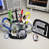
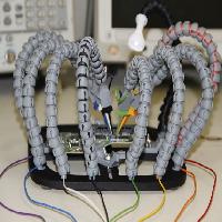
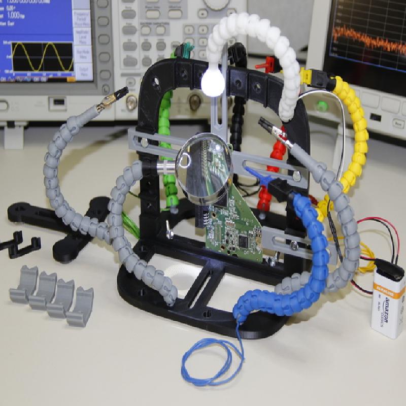
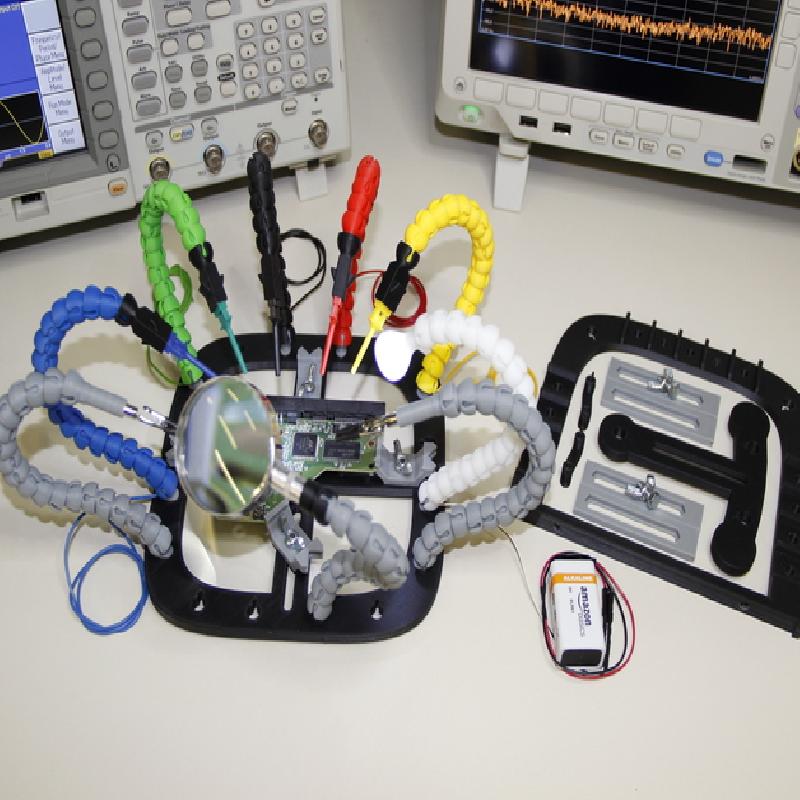
The "PCB Workstation" is the only tool you really need to make stable connections to the pins of the electronic components on your Printed Circuit Board.
See "Instructions page" for details about this project.
HAVE A LOOK AT THE ARTICLE PUBLISHED ON MAKE MAGAZINE:
http://makezine.com/projects/3d-print-the-ultimate-helping-hands-for-a-pcb-workstation/
"PCB Workstation" in the TOP 8 CLEVER JIGS on MAKE MAGAZINE:
http://makezine.com/2015/12/13/8-clever-jigs-for-your-workshop/
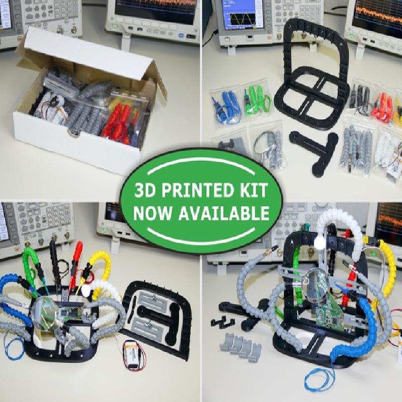
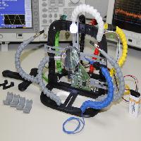
For everyone who doesn't have a 3D printer or simply want to get a fully functional PCB Workstation with a large set of printed parts and hardware accessories, it is now available a ready to use HIGH QUALITY 3D PRINTED KIT!
Parts and accessories included in the Standard Kit:
http://www.thingiverse.com/download:1870663
HOT UPDATE: It is now available an advanced version of the kit: "PCB WORKSTATION - SPECIAL LAB EDITION"
This new kit is the perfect solution for your electronic laboratory, expecially if you need to do complex analysis of electronic boards using micro spring probes or micro SMD hooks, such as CHIP-OFF or JTAG analysis of mobile phones and more.
Email me at "giuseppe.finizia@gmail.com" if you need any info about the kits.
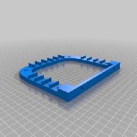
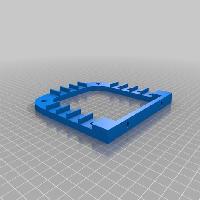
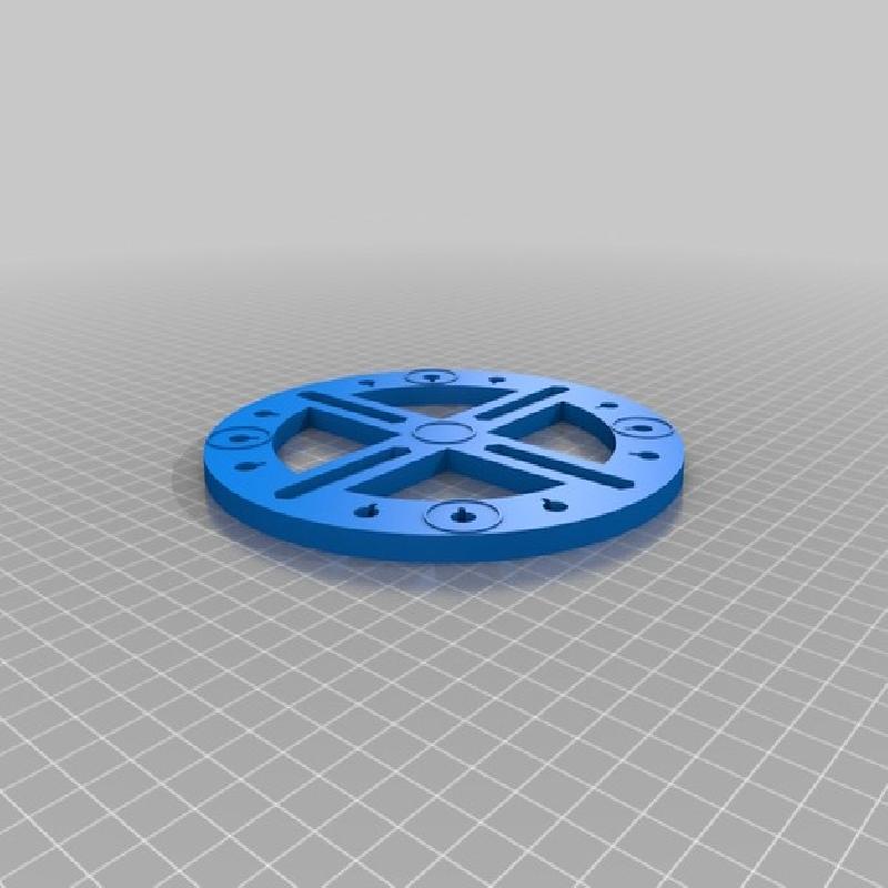
This kit provides multiple types of bases, so you can choose the one that best suits your needs.
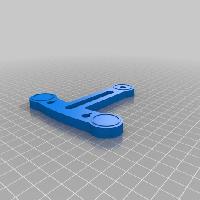
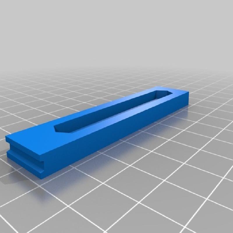
The new piece "Base_Extension.stl" can be used to allow the mounting of bigger PCBs that do not fit onto a base. This piece can be coupled with each available base (except "Base_round16cm_12holes.stl") using the appropriate "extension linkage" piece supplied in the archive "Extension_Linkages.zip".
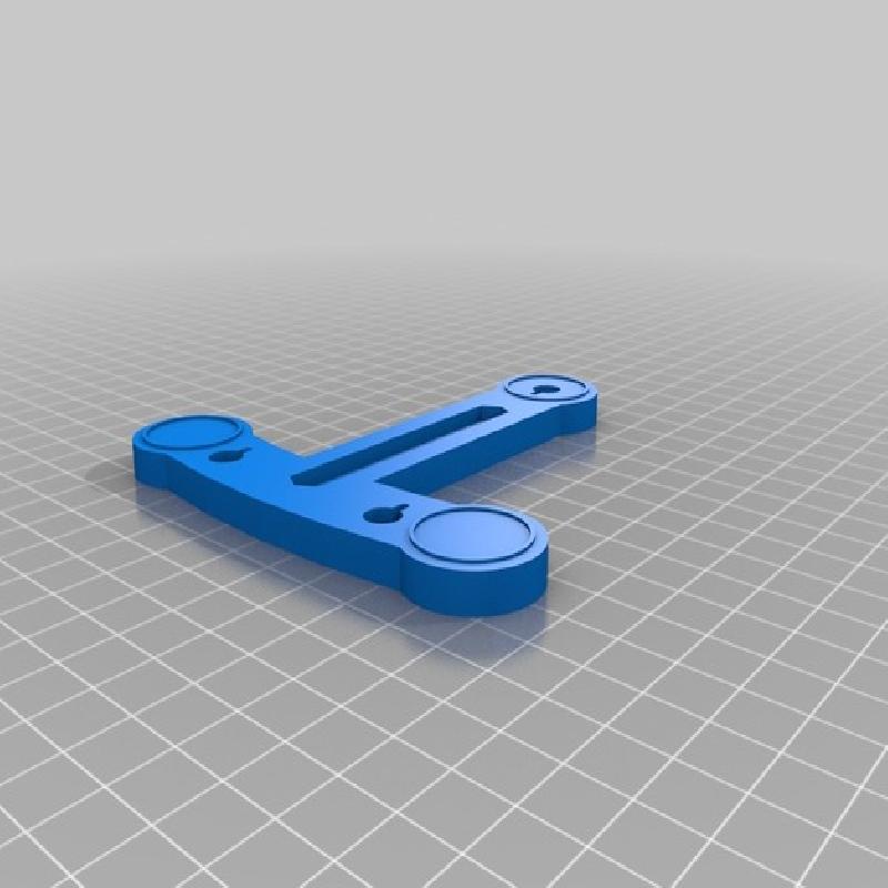
Using the piece "Bases_Linkage.stl" it is possible to connect two or even more bases together to allow working on big Printed Circuit Boards. This is an universal piece and it can be used with all the available bases except "Base_round16cm_12holes.stl".
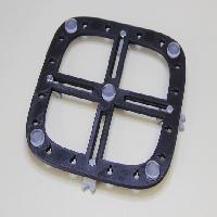
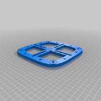
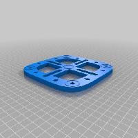
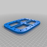
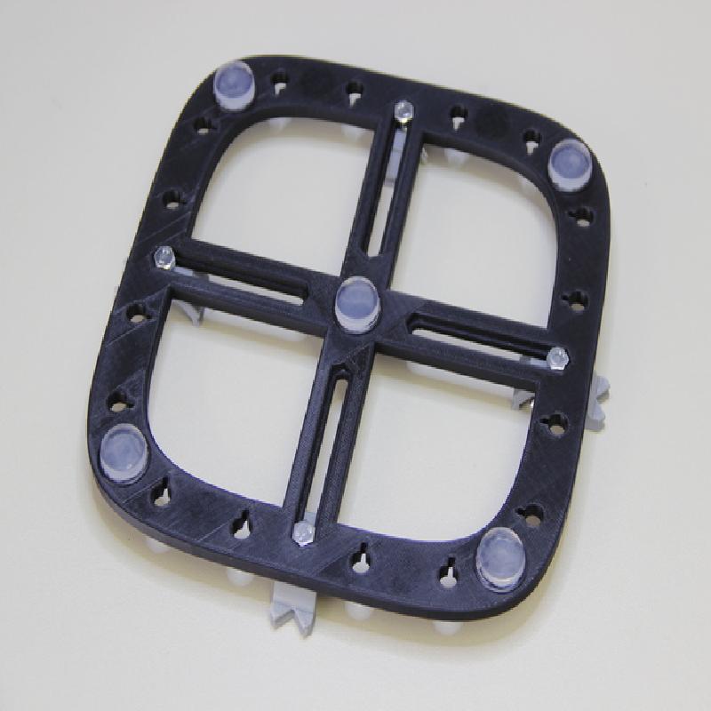
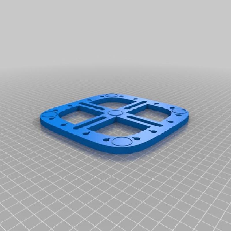
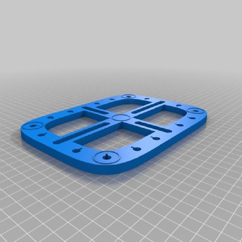
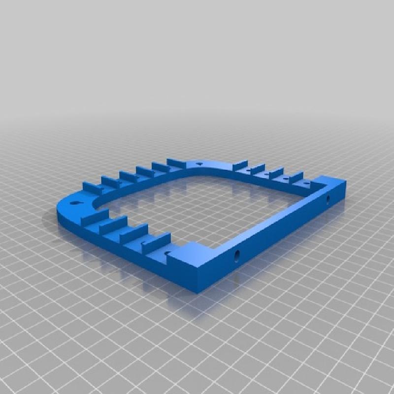
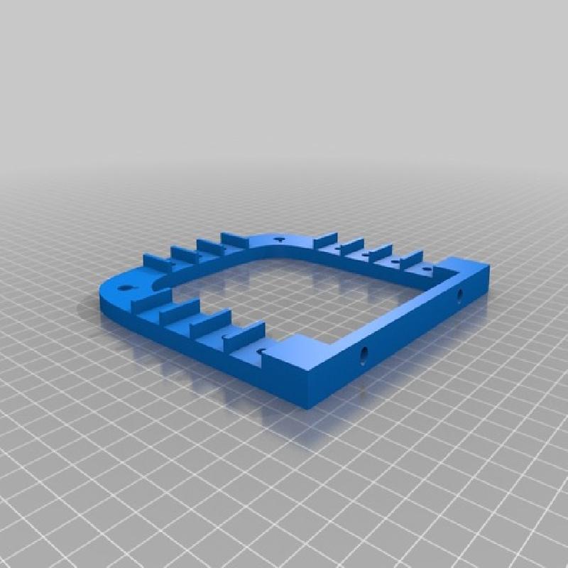
The bases are equipped with multiple holes in which can be inserted a variable number of articulated arms for different purposes.
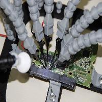
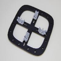
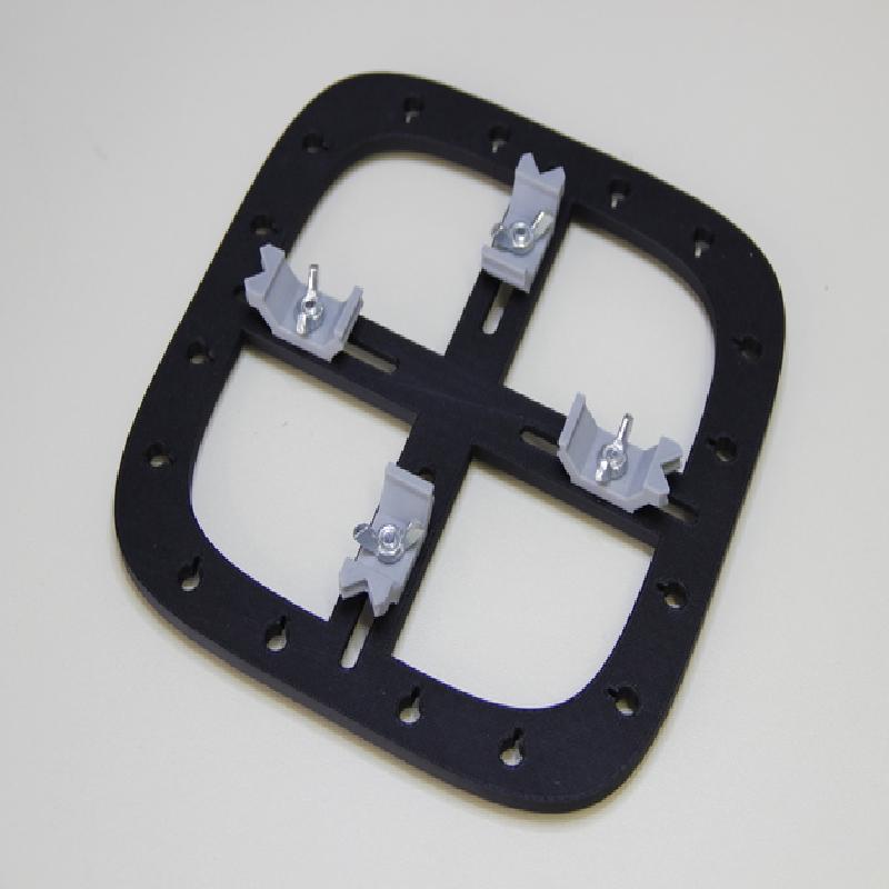
The central part consists of 4 slides arranged in a cross along which can be moved the anchoring blocks to firmly keep in place the printed circuit board.
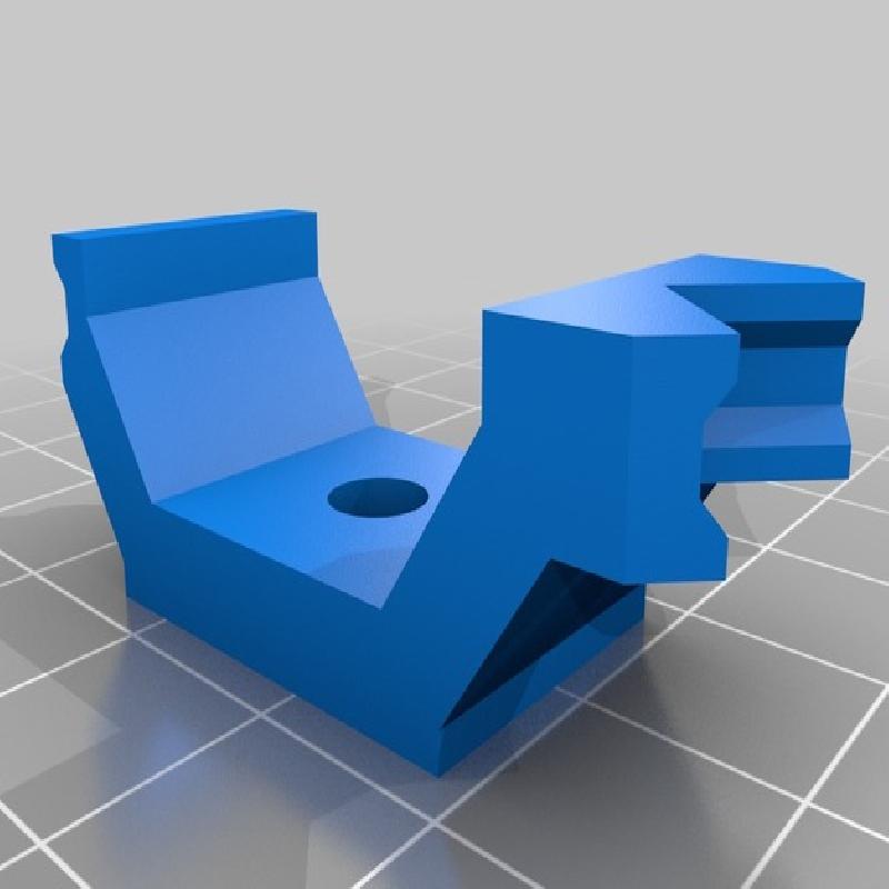
The anchor blocks have two faces, one for straight sides, the other for the corners of a printed circuit board. You can choose the right face simply turning the anchor block. The anchor blocks are fixed to the base by means of wing nuts (5 mm) and hex bolts (5 x 12 mm).
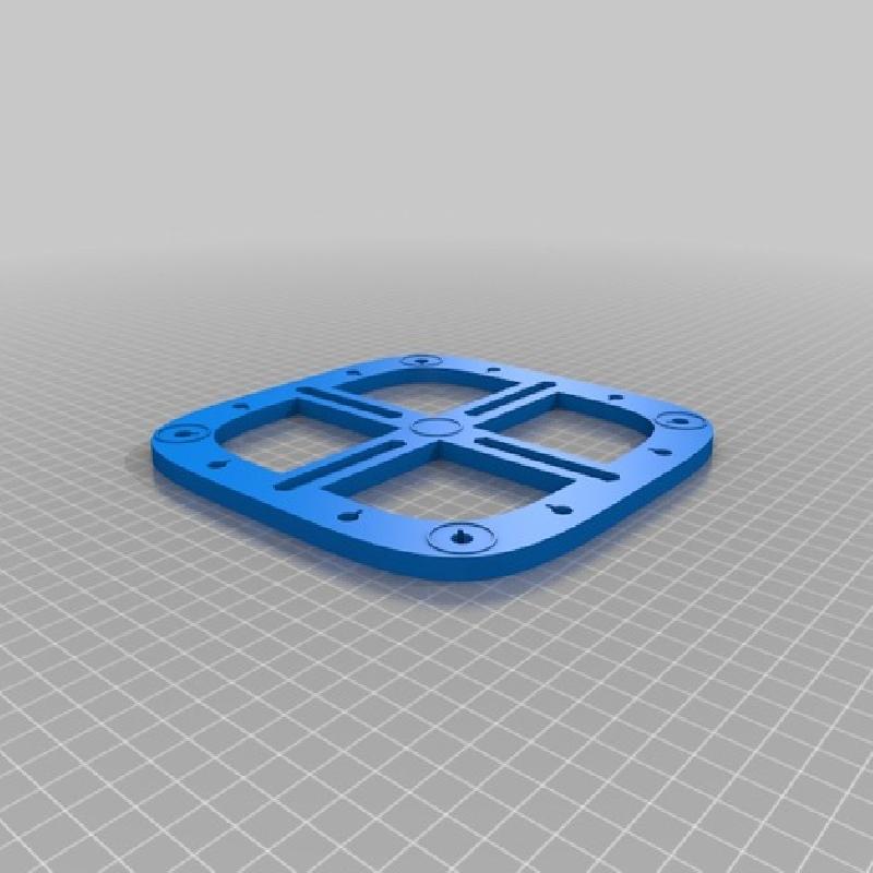
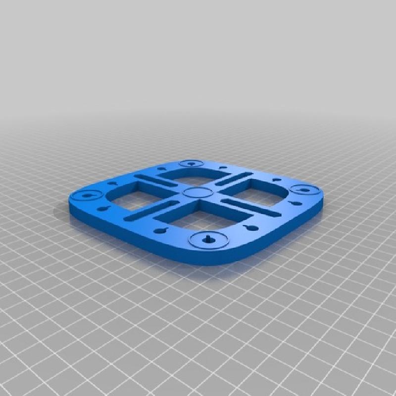
On the lower face of the base there are 5 guidelines for the precise positioning of silicone bumpers.
The base should be printed upside-down, in this way it is not required the use of support structures to support the overhanging parts of the central slides.
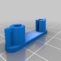
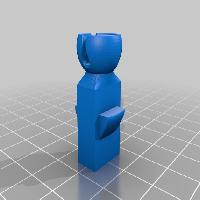
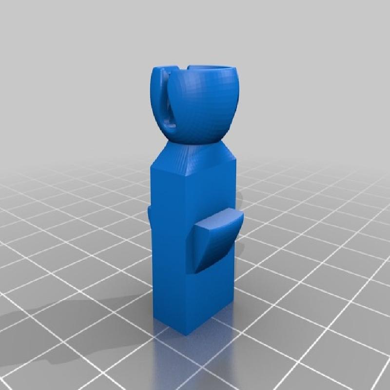
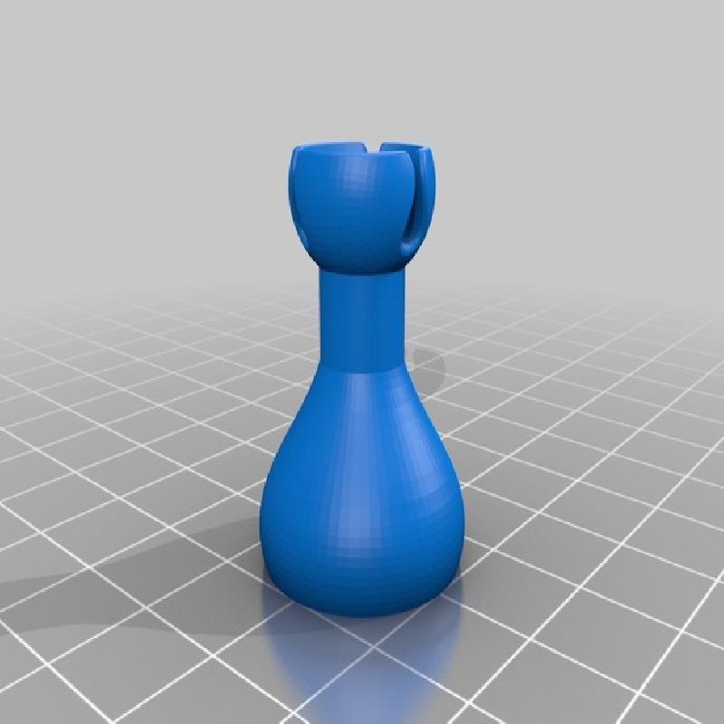
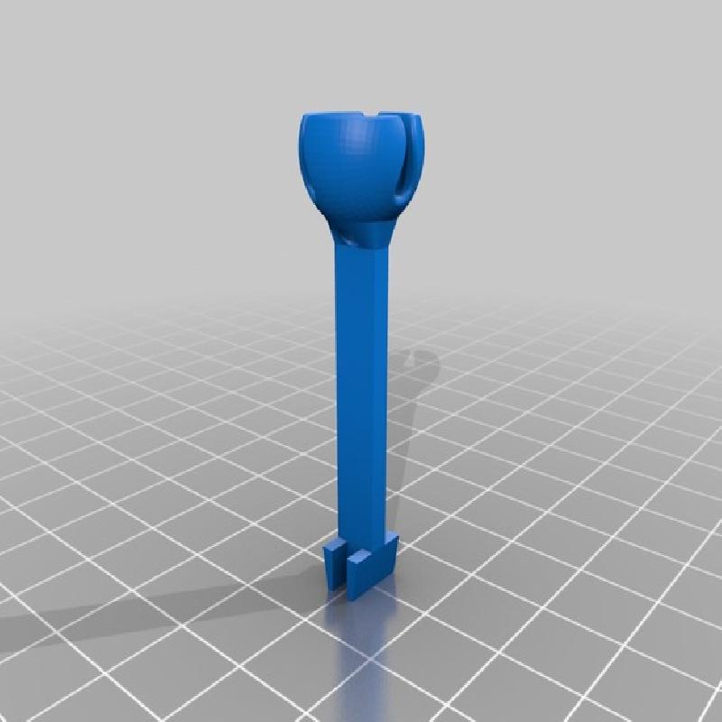
Each articulated arm is composed of a first element to be inserted in a hole of the base. This piece has a slot to allow the passage of the electric cable without passing through the hole of the base, so it is very easy to insert, remove or change an articulated arm on the fly.
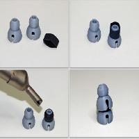
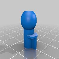
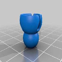
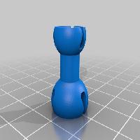
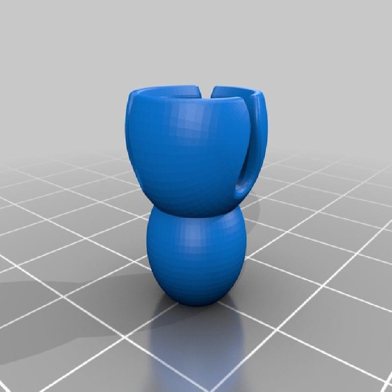
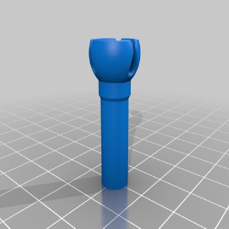
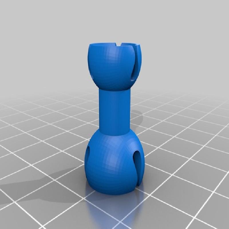
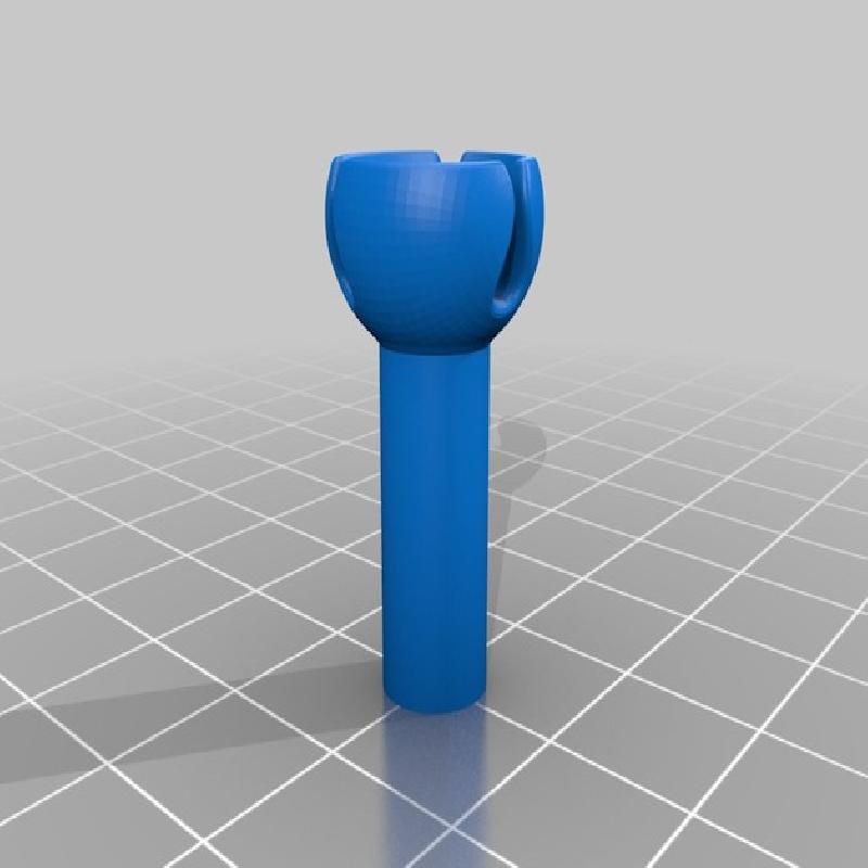
The articulated arms are then made assembling multiple ball and socket joints. Depending on the required length, an articulated arm may be formed of a variable number of ball and socket joints, however 18-20 elements should be sufficient to most of uses. Each articulated arm provides an internal duct in which an electric cable can run.
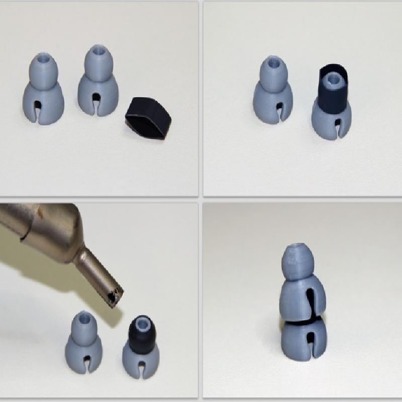
If you wish to make more rigid articulated arms, you can use the provided special ball and socket joints that have a slightly smaller ball to allow the application of a rubberized coating that improves the friction and the stability of the articulated arms. I suggest the use of a small piece of heat shrink wrap 8 mm (0,28 inches) long, 0,27 mm (270 micron) thick and 9 mm (0,4 inches) diameter.
Moreover, it has been recently added the new piece "B&S Joint (thick coated).stl" to allow the use of a thicker heat shrink tube.
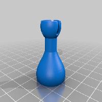
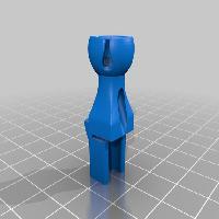
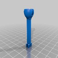
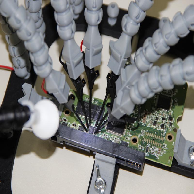
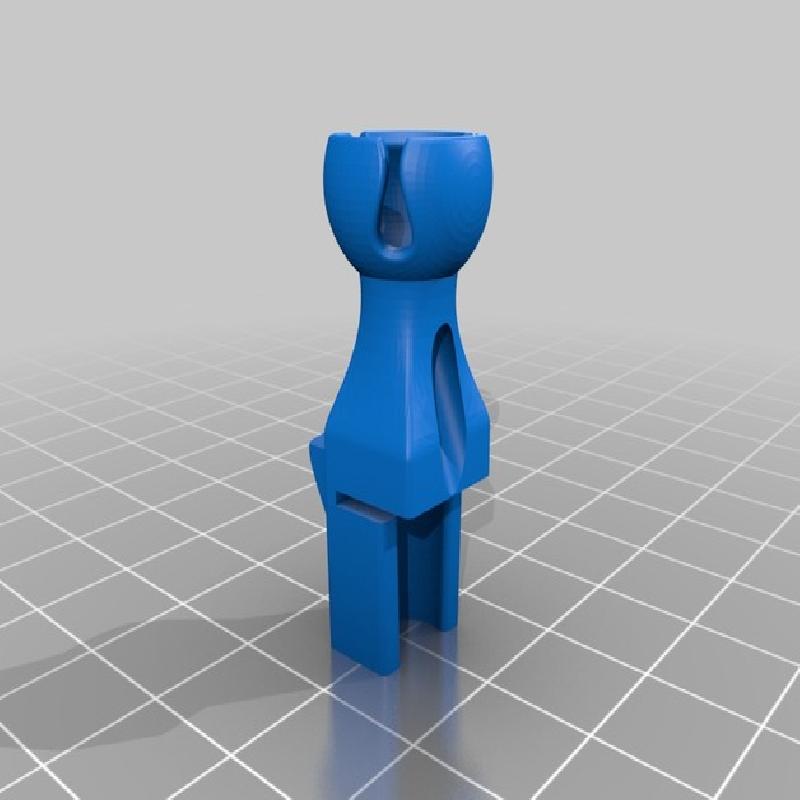
The terminal elements of the articulated arms are designed to accommodate different types of accessories:
Alligator Clips (https://www.sparkfun.com/products/12033)
IC Hook Clip Grabbers (http://www.amazon.com/12pcs-6colors-Small-Grabbers-Multimeter/dp/B00C4PLQ7A)
Micro SMD Grabber Test Clips (http://www.digikey.com/catalog/en/partgroup/micro-smd-grabber-72902-series/16004)
Micro Spring Probes (http://uk.rs-online.com/web/p/needle-point-probes/0775726)
Micro Clip Probes (http://uk.rs-online.com/web/p/grabber-clips/0775704)
Zeroplus type Probes (http://www.amazon.com/Probe-Saleae-Logic16-Zeroplus-analyzers/dp/B005NR440W)
Tektronix type Probes (Part number 020-2733-00 in kit 020-2662-0x - http://www.bmisurplus.com/products/40893-tektronix-p6516-logic-probe-accessory-kit-020-2662-00)
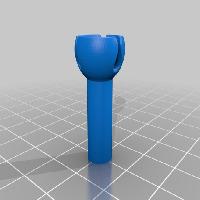
There is also a terminal element that can accommodate a LED to illuminate a particular area of the PCB. I used a super bright white LED (https://www.sparkfun.com/products/531) connected to a 9V battery using a 220 Ohm resistor.
Moreover, now that you have this "PCB Workstation" perhaps you will no longer use the old "third hand tool", but you could miss the "magnifying glass"... So, here is a new special piece (Holder_Magnifying_Glass.stl) to still use the accessories of the old third hand tool, including the magnifying glass.
The proposed Alligator Clip is mounted on its terminal element using a screw that is mounted in the hole accessible from the spherical socket. Using Alligator Clips could be useful when you need to hold a circuit board having quite large electronic components that does not allow the holding of the PCB between the anchor blocks of the base.
The terminal element designed for Micro Test Clips can keep up to two grabbers, one per side, so allowing the connection of multiple test clips to IC pins very close to each other.
Each part of this kit should be printed exactly as it appears in the preview image, in this way you get the best orientation of each piece with the minimal use of support structures.